- 13 -
c. AFC Check.
After adjustment ,it is necessary to confirm the DC voltage across R603 when changing the RF output frequency of
pattern generator (PM5518) by ±0.1MHz, the DC voltage should be as following:
Remark: IF=38.9MHz .
If Q.C. checked AFC voltage on the production, the AFC voltage should be 2.4±0.5V. If the
result is not satisfactory, repeat adjustment step ‘b. Adjustment step’ until correct voltage
is obtained.
iv. Adjustment for H position and V position, V-height and V linearity.
a. Receive pattern signal (PAL).
b. Enter ADJUST MENU.
1. Adjust value of HOR.POS to get a good H position picture.
2. Adjust value of VER.HEI to get a normal picture.
3. Adjust value of VER.POS to get a good V position picture.
4. Normal VER.LIN and VER.S CUR isn’t need adjust. If V linearity is not good, please adjust value of VER.LIN and
VER.SCUR to get a good V linearity picture.
c. Receive pattern signal (NTSC).
d. Enter ADJUST MENU
1. Adjust value of HOR.POS60 to get a good H position picture.
2. Adjust value of VER.H60 to get a normal picture.
3. Adjust value of VER.POS60 to get a good V position picture.
4. Normal VER.LIN60 and VER.SC60 isn’t need adjust. If V linearity is not good, please adjust value of VER.LIN60 and
VER.SC60 to get a good V linearity picture.
v. Adjustment for TV TINT (TV picture) and AV TINT (AV picture)
(step a~d is only for MFxx models)
a. Receive a NTSC color bar pattern signal from RF.
b. Press key “I.P.C.” to set contrast, Brightness, Color and Tint at normal position.
c. Put the Probe of Oscilloscope to “B-out” Terminal of IC201 PIN 12.
d. Enter ADJUST MEMU
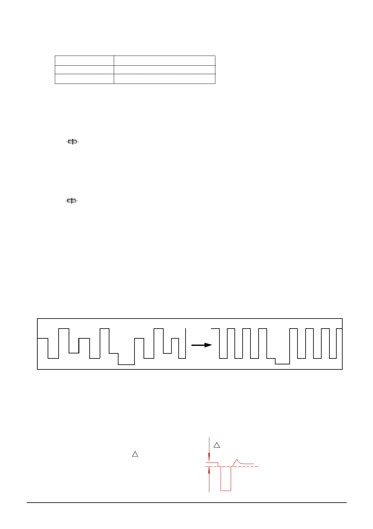
Adjust Value of SUBTINT and Notice the Waveform Change Until the Waveform is shown as below:
e. Receive a NTSC Color bar Signal from AV.
f. Enter ADJUST MENU
Adjust the Value of AV S TINT until the Waveform of Oscilloscope is shown as above.
vi. Adjustment for SECAM BL (only for MFxx or use NN5198K models)
a. Receive a SECAM dot pattern signal from RF.
b. Press key “I.P.C” to select “NATURAL” status.
c. Put the Probe of Oscilloscope to “B-out” Terminal of IC201 Pin12 and GND. (Probe: 10:1,
Oscilloscope VOLTS / DIV: 20mv / DIV.
d. Enter ADJUST MENU.
Adjust Value of SECAM BL until V is smallest.
v
RF FREQUENCY DC VOLTMETER INDICATION
IF + 0.1MHz 1.2 ± 0.5V
IF - 0.1MHz 3.3 ± 0.5V
 Loading...