# VSH400PLC090909
5. Return to the basic screen of the panel by taking out the locating insert (2) or
the offset insert (3) [Fig.26]
6. Check whether the hole is correctly made with the proper distance from the
edge of the bus
7. If necessary, scale the system of the counter L again
Zero adjusting of the length measurement system (counter L2)
1. Perform the steps 1-5 from the point ”Scaling of the cut bus length”
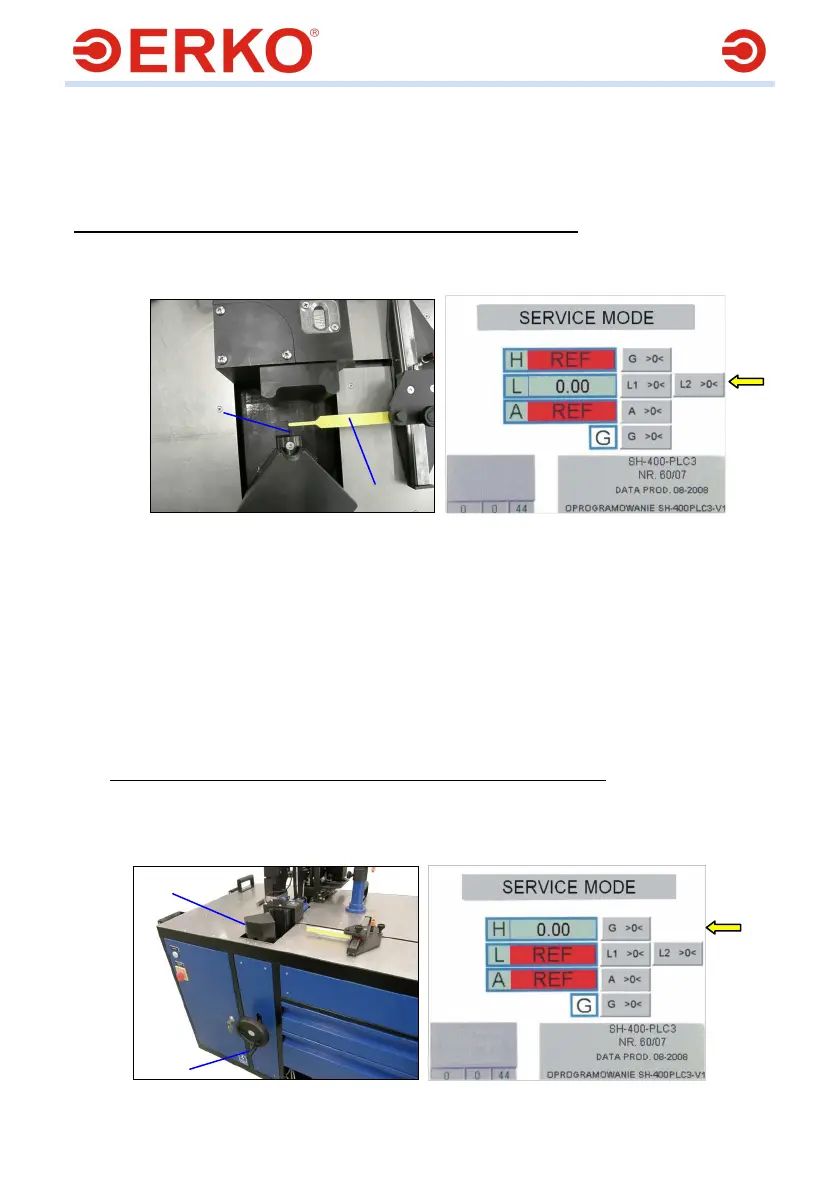
Make a move with the measurement system L (4) [Fig.26] till the moment the
inscription REF on the counter L [Fig.34a] vanishes
Fig.33a Fig.34a
2. Move the lever measurement system to the second measurement range
3. Put the standard section of 1 m length (3) [Fig.33a] between the basing insert
(2) and the measurement lever (1)
4. Holding the immobilized lever on the panel press the pushbutton L2 >0< at
the height of the counter L
5. Return to the basic screen of the panel by taking out the locating insert (2) or
the offset insert (3) [Fig.26]
6. Check whether the hole is correctly made with the proper distance from the
edge of the bus
7. If necessary, scale the system of the counter L again
Zero adjusting of the height measurement system (counter H)
1. Perform the steps 1-5 from the point ”Scaling of the cut bus length”
2. Make a move with the body (2) of the measurement system H using the crank
(1) [Fig.35] till the moment the inscription REF on the counter H [Fig.36]
vanishes
Fig.35 Fig.36
2
1
2
1