# VSH400PLC090909
11. Return to the basic screen of the panel by taking out the locating insert (2) or
offset insert (3) [Fig.26]
12. Check correctness of cutting
13. If necessary, scale the system of the counter G again
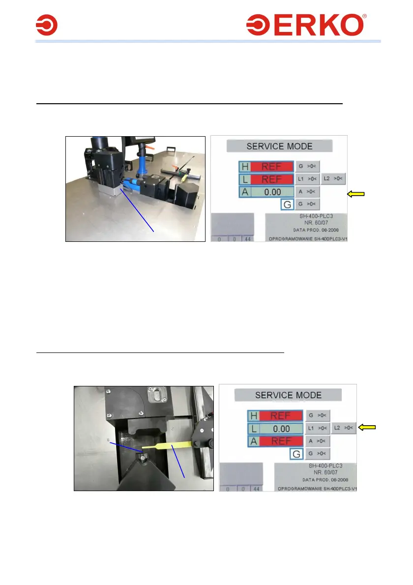
Zero adjusting of the insert for measurement of the bending angle (counter A)
1. Perform the steps 1-5 from the point ”Scaling of the cut bus length”
2. Make a move with the levers (1) of the measurement insert [Fig.31] till the
moment the inscription REF on the counter A [Fig.32] vanishes.
Fig.31 Fig.32
3. Using, for example, a straight piece of bus, position the levers (1) in a position
parallel to the body of the measurement insert.
4. Holding the immobilized levers (1) [Fig.31] on the panel [Fig.32] press the
pushbutton A >0< at the height of the counter A
5. Return to the basic screen of the panel by taking out the locating insert (2) or
the offset insert (3) [Fig.26]
6. Check the correctness of bending
7. If necessary, scale the system of the counter A again
Zero adjusting of the length measurement system (counter L1)
1. Perform the steps 1-5 from the point ”Scaling of the cut bus length”
2. Make a move with the measurement system L (4) [Fig.26] till the moment the
inscription REF on the counter L [Fig.34] vanishes.
Fig.33 Fig.34
3. Move the measurement lever (1) till the vertical axis of the locating insert (2)
[Fig.33]
4. Holding the immobilized lever on the panel press the pushbutton L1 >0< at
the height of the counter L
1
2
1