GB-4
GB
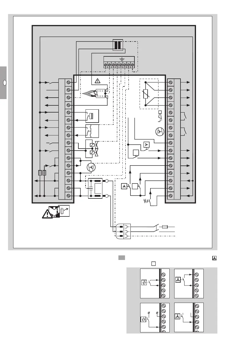
Burner control unit BCU connection diagram
12345678910111213141516
17 18 19 20 21 22 23 24 25 26 27 28 29 30 31 32
PE
N (L2)
L1 (L1)
F1
F2
V2V1
WF
24 V
0 V
ϑ
ϑ
IZ
PE
BCU 300:THP-G
DG
max. 2 A,
253 V
max. 5 A,
253 V
N
F1 T 8A H
F2 T 3,15A H
IEC 60127-2/5
N
AC/DC
ϑ
35453625
▷ In order to ensure post-cooling, the heater con-
stantly requires 230 V AC.
Connecting the room thermostat for “Heating”
and “Controlled air flow” mode
▷
Use a room thermostat with a hysteresis of ±1°C.
It switches on if the room temperature is 1°C
less than the set temperature and switches off
again once the room temperature is 1°C more
than the set temperature.
▷ Do not directly connect the room thermostat to
terminals1 and3.
5 Connect the terminals for Controlled air flow
and Heating
.
31 3229 3028
31 3229 3028
0
26 27
24 2523
0
26 27
24 2523
230 V ~
230 V ~
+24 V =/~
+24 V =/~
+24 V =/~
+24 V =/~
 Loading...