GB-5
GB
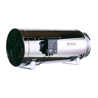
Connecting multiple heaters to a single room
thermostat
▷ Phase reversal will result in a short-circuit.
▷ Do not install different phases of a three-phase
current system at the inputs if the voltage be-
tween the phases exceeds 230V (+10%).
▷
Multiple heaters must be wired to the thermostat
via a relay.
29
K3/1
K3
24 V=/230 V~
230 V~
230 V~
230 V~
30
1. GP
29 30
2. GP
29 30
3. GP
K3/2 K3/3
▷
At 24VDC/AC, multiple heaters can be con-
trolled in parallel.
▷ Note the polarity!
230 V~
24 V=/~
1. GP
26 2725
2. GP
26 2725
26 2725
3. GP
▷
Do not directly connect the thermostat to mul-
tiple heaters.
▷
Do not connect terminals28, 29 and30 directly
to the next heater. A short-circuit can occur due
to different phases and polarities.
29 30
1. GP
29 30
2. GP
29 30
3. GP
29 30
3. GP
28 29
1. GP
30 28 29
1. GP
30 28 29
1. GP
30 28 29
1. GP
30
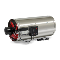
Reset, alarm, external fan
▷
For external fault signalling, an external
alarm
and an external reset button
can be connected.
N L1
31 3229 30
230 V ~
max. 2 A
230 V ~
6 For improved air circulation in the room, an ad-
ditional fan
can be connected.
N L1
253 V AC
max. 5A
▷ In case of a power failure, an emergency power
supply unit should automatically take over the
power supply. Emergency power supply units
with a cardan shaft drive for tractor attachment
are also suitable.
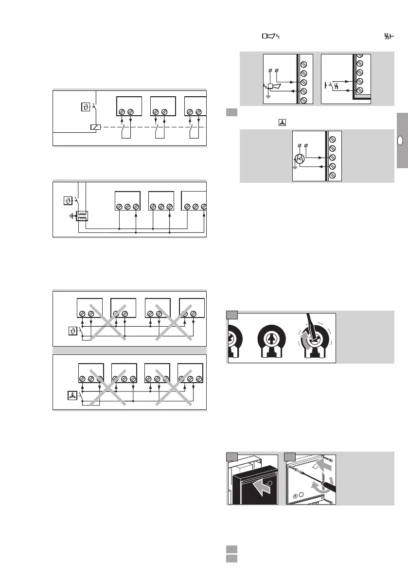
Adjusting the switch-on delay t
E
▷
If multiple heaters switch on at the same time,
there can be a gas and/or power shortage on in-
dividual devices. To avoid this happening, adjust
the switch-on delayt
E
using the potentiometer
in the upper housing section of burner control
unitBCU.
▷ The potentiometer is set to 0s at the factory.
t
N
t
M
0
1
0
2
0
3
0
4
0
5
0
6
0
t
E
▷ We recommend using a switch-on delayt
E
of 5
to 10s between each device.
▷
The post-cooling timet
N
is set to 50s at the
factory and the minimum burner on timet
M
to
0s. These values must not be changed.
▷
Once the wiring is complete, close the BCU
again. Ensure that the upper housing section is
not inclined when being replaced on the lower
housing section.
98
▷
To guarantee that the burner control unit com-
plies with enclosure IP54, make sure that the
screws are tightly secured after wiring and that
the cable glands are closed.
0 Switch on the power supply.
Release the gas supply.
 Loading...