GB-7
GB
▷
The inlet pressurep
u
must comply with the tech-
nical data, see page17 (Technical data).
7 Switch on the burner control unit. Press the
ON/OFFbutton
OFF 1
2
3
4
5
AUTO
+ AUT
MODE
(RESET)
ON/OFF
O
until an LED lights up.
8 Select the Heating
OFF 1
2
3
4
5
AUTO
+ AUT
MODE
(RESET)
ON/OFF
O
operating mode.
9 Let all heaters burn for at least 20s.
▷
The required gas pressure on the burner depends
on the lower calorific value/Wobbe index.
0 Select the required gas pressure on the burner
from the table.
Lower
calorific
value
Wobbe
index
[mbar]
[MJ/m
3
]
Natural gas L G25 32.49 41.53 9.2
Natural gas H G20 37.78 50.71 6.3
LPG G 30 125.81 87.34 24.0
▷
Converting the lower calorific value/Wobbe index
to kWh/m
3
:
kWh/m
3
=
Lower calorific value/Wobbe index [MJ/m
3
]
3.6
▷
Always use a pressure gauge to adjust the burner
gas pressure. The white scale on the adjusting
screw may differ.
If all heaters are heating at the same time, com-
pare the required gas pressure on the burner
with the gas pressurep
G
read off the pressure
gauge, adjust it and monitor the pressure gauge.
p
G
0
p
G
2,5 mm
Flame signal
▷ The flame signal is displayed for 20s.
Check the flame signal.
▷
For adjustment and maintenance work, the flame
signal can be displayed.
▷
Display of the flame signal starts when the se-
lection button is pressed and within 1s (almost
simultaneously), ON/OFF
OFF 1
2
3
4
5
AUTO
+ AUT
MODE
(RESET)
ON/OFF
O
is pressed, too.
● = LED is constantly lit
○ = LED flashes
µA
2 3 4 6 8 10 12 14 16 18 20
OFF 1
2
3
4
5
AUTO
○ ●
○ ● ● ●
○ ● ● ● ● ●
○ ● ● ● ● ● ● ●
○ ● ● ● ● ● ● ● ● ●
▷
The flame signal is sufficient when 2LEDs are
constantly lit and the third LED flashes.
▷
If the flame signal is not sufficient, see page9
(Assistance in the event of malfunction).
Monitor combustion.
▷ The flame must be blue and must remain inside
the device.
▷ If the burner pressurep
G
and flame signal have
been checked and adjusted on all devices, the
system operates correctly.
4 Remove the pressure gauge.
0
p
G
5 Close the test nipple.
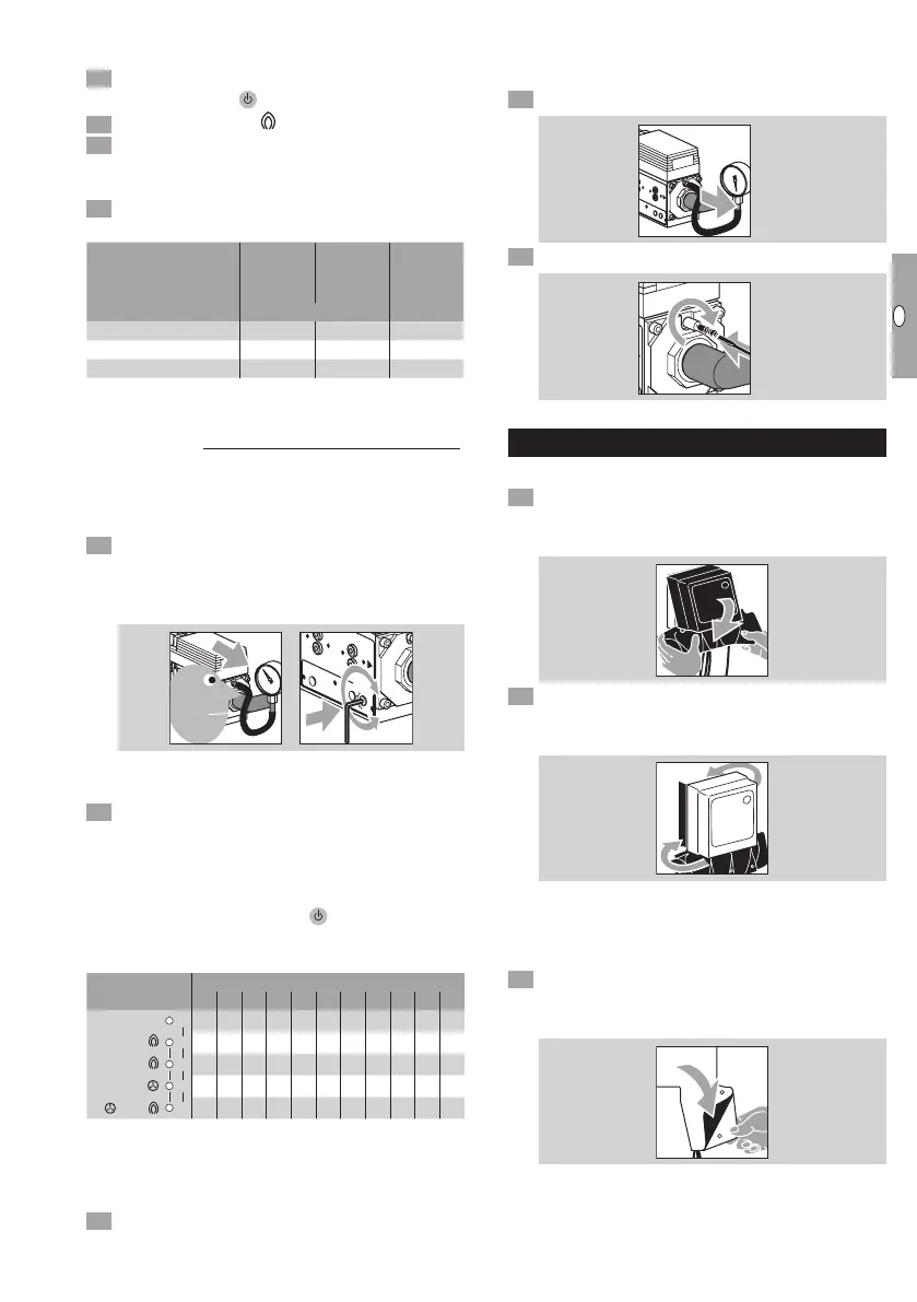
Installing the protective caps
Burner control unit
Pull the opened protective cap from the top over
the burner control unit. In doing so, pull the edges
of the protective cap apart.
ON
/
O
F
F
(
R
E
SET
)
MO
DE
OFF
AU
TO
+AU
TO
Slide the opened edges of the protective cap into
the gap between the burner control unit and the
mounting plate.
ON
/
O
F
F
(
R
E
SET
)
MO
DE
OFF
AU
TO
+AU
TO
▷
When it becomes difficult to move the edges
of the protective cap, this means the material
has turned cold and hard. The protective cap
will become soft again when it is heated briefly.
Hold the ends of the protective cap on the back
of the burner control unit together and close the
push-in rivets.
ON
/
O
F
F
(
R
E
SET
)
MO
DE
OFF
AU
TO
+AU
TO
 Loading...