6
S1
RL1 RL2
1
2
3
5
6
8
10
11
13
LEARN
POWER
HALL
SW1
1
2
3
4
5
6
7
8
9
10
11
12
13
VCC
GND
SPEED
RSD
P287Z
VR1 VR2 VR3 VR4
F1
L
N
PE
PE
L
N
LAMP
POWER
MOTOR
CAPACITOR
MOT1
MOT2
COM
CTSR800EC: 16uF; CTSR800ECM: 55uF
VCC
GND
SPEED
F1
(12VDC)
M1
CLOSE
OPEN
STOP
LOOP
FCC
FCA
CTSR800EC: 230V / 50Hz
CTSR800ECM: 125V / 60Hz
N
L
ANT
SG.C (FT1)
COM
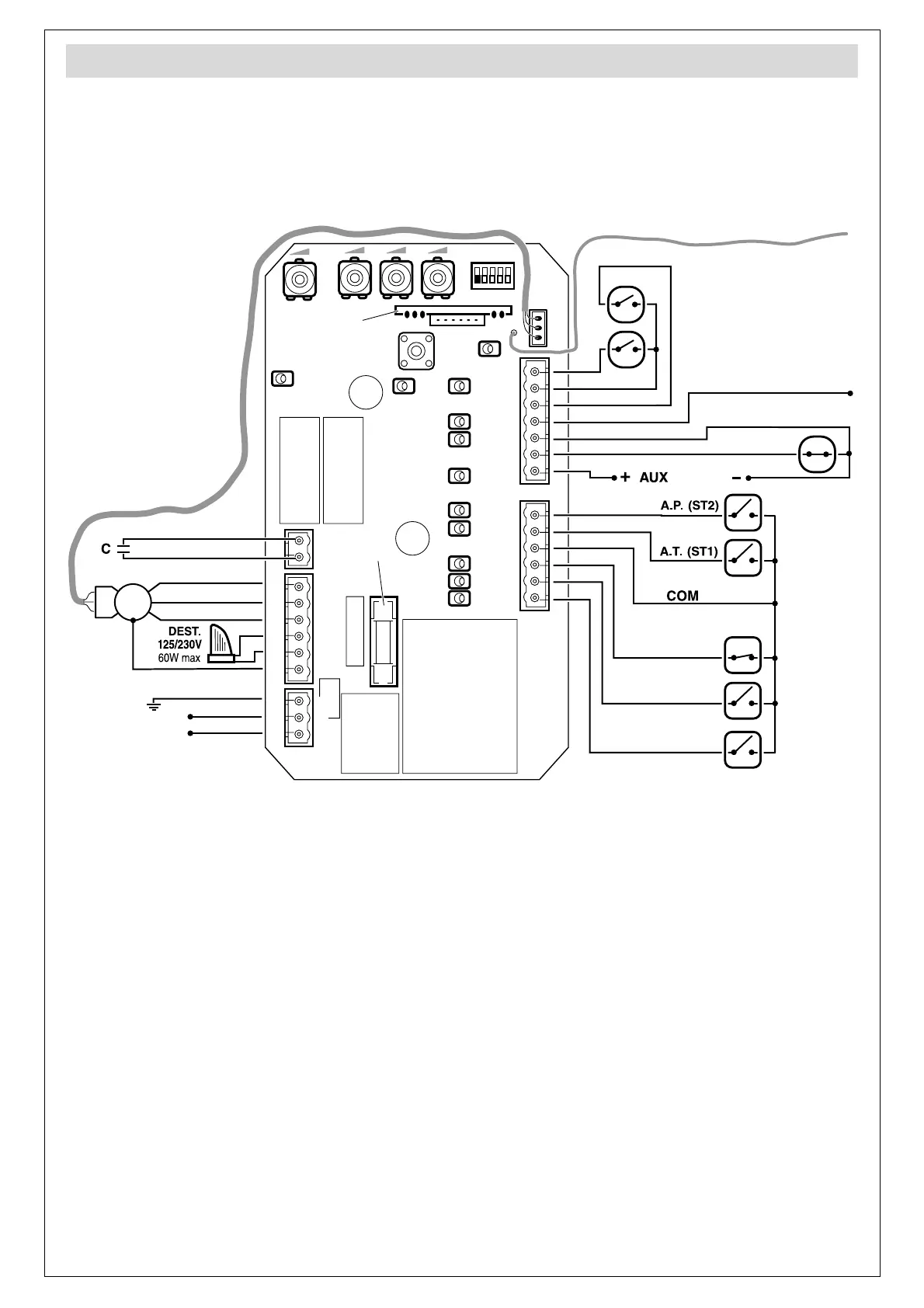
General connections
LEDs:
POWER Power connected
LEARN Radio programming
LED 1 “CLOSE” pushbutton enabled
LED 2 “OPEN” pushbutton enabled
LED 3 “STOP” pushbutton enabled
LED 5 ST1 pushbutton enabled
LED 6 ST2 pushbutton enabled
LED 8 SG.C Photocell enabled
LED 10 Loop detector (LOOP) enabled
LED 11 Closing Limit Switch (FCC) enabled
LED 13 Opening Limit Switch (FCA)
enabled
Fuse
F1 10A fuse
Ensure the power supply is disconnected
before making or changing the connection.
When the connections are complete, return the
control panel cover.
• The panel has a built-in radio receiver (RSD) to
receive transmitter signals at 433.92MHz.
Connectors:
CLOSE (1) Close Pushbutton
OPEN (2) Open Pushbutton
STOP (3) Stop Pushbutton
COM (4) Pushbutton Common
A.T. (5) Total Opening Pushbutton
A.P. (6) Pedestrian Opening Pushbutton
AUX (12VDC) (7) 12Vdc Auxiliaries supply
SG.C (8) Closing safety device (photocell)
COM/ GND (9) Safety Device Common /
12Vdc Auxiliaries supply mass (–)
LOOP (10) Magnetic loop detector
FCC (11) Closing Limit Switch
COM (12) Limit Switch Common
FCA (13) Opening Limit Switch
NOTE: installation can be carried out in two different ways:
either using the three “OPEN” (1), “CLOSE” (2) and “STOP”
(3) connectors or using the “A.T.” connector. When using
the latter, it runs sequentially to avoid cyclical Open-Stop-
Close orders.