EasyManua.ls Logo

Erreka DINGO - User Manual

Erreka DINGO
4 pages
Print Icon
To Next Page IconTo Next Page
Loading...
5
DINGO
Quick installation and programming guide English
WARNING
This quick guide is a summary of the complete installation manual. The manual contains safety warnings and
other explanations which must be taken into account. The most recent version of this guide and the
installation manual are available at the "Downloads" section on Erreka's website:
http://www.erreka-automation.com
The options and functions described in this guide apply for the firmware version indicated on the circuit. The
firmware, as part of a process of continuous improvement, is subject to new functionalities or upgrades being
included as a result of new versions which are not necessarily compatible with previous ones. For this reason,
some options or functions may differ or be unavailable if your firmware is older than shown in this guide.
Electrical wiring
A: Main power supply
B/E: Flashing light with
antenna
C: Photocells (Tx / Rx)
D: Pushbutton/wall key
E259A
Install the rack at a height between 75 and 95 mm.
90 mm is recommended as the reference height.
Elements of the complete installation
Assembly levels
180º
D259A
180º
D259B
Unlocking
Motorised operation locking:
Insert the key and turn it anti-clockwise 180º as far as
it will go. The pinion will return to its work position, in
contact with the rack.
Activate a key device in order for the gate to carry out
a "reset".
Unlocking Locking
Unlocking for manual operation:
Insert the key (1) and turn clockwise 180º without
forcing it: the rack drive pinion will come down from
its operating position, releasing the rack.
MSM-043/01
Firmware V1.0 or later

Other manuals for Erreka DINGO

Question and Answer IconNeed help?

Do you have a question about the Erreka DINGO and is the answer not in the manual?

Summary

Important Safety Warning

Elements of the complete installation

Electrical wiring

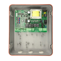
Details electrical connections for main power, light, photocells, and pushbutton.

Assembly levels

Specifies mounting heights and rack positioning for optimal gate operation.

Manual Operation: Unlocking and Locking

Unlocking for manual operation

Procedure to release the rack drive pinion using the key for manual gate control.

Motorised operation locking

Procedure to re-engage the pinion for motorised operation using the key.

General connections

Display indications

D1 and D2 indicators

Meaning of static and flashing codes for gate status and operations.

D3 and D4 indicators

Meaning of static and flashing codes for safety devices and battery status.

Programming Functions

Turning direction change and check

Procedure to verify and adjust motor turning direction after a reset.

Total opening radio code programming

Procedure for programming radio transmitters for total gate opening.

Pedestrian opening radio code programming

Procedure for programming radio transmitters for pedestrian gate opening.

Open;close programming

Procedure to program the gate's open and close cycle using a transmitter.

Complete programming chart

Motor turning direction

Setting for the direction of motor rotation.

Opening safety device

Configuration for photocell or strip safety devices.

Closing safety device

Configuration for photocell or strip safety devices for closing.

Radio receiver

Selection between RSD card or twin-channel decoder card.

Total opening radio code programming

Parameter for programming radio code for total opening.

Pedestrian opening radio code programming

Parameter for programming radio code for pedestrian opening.

Gate travel programming

Parameter for setting the gate's travel limits.

Functioning mode

Selection between Automatic and Step-by-step operation modes.

Standby in automatic mode

Setting duration for standby in automatic mode.

Pedestrian opening

Setting the percentage for pedestrian opening duration.

Flashing light

Configuration for flashing light operation.

Garage light time

Setting the duration for the garage light.

Gate speed

Setting for the main gate opening and closing speed.

Slow down speed

Setting for the gate's slow down speed.

Slowdown distance

Setting for the distance at which the gate slows down.

Reverse after closing

Setting for gate reversal after closing to offset expansion.

Maximum force

Setting for the maximum force exerted by the motor.

Closing photocell used during standby

Configuration for closing photocell during standby.

Pushbutton operation during standby

Configuration for pushbutton operation during standby.

Opening mode

Setting for the gate's opening mode (e.g., collective, step-by-step).

Operations carried out

Indicates the number of cycles completed.

Erreka DINGO Specifications

General IconGeneral
BrandErreka
ModelDINGO
CategoryGate Opener
LanguageEnglish

Related product manuals