S0740 800 191/E080229/P78
-- 2 --TOCe
Rights reserved to alter specifications without notice.
READ THIS FIRST 4.................................................................
INTRODUCTION 5...................................................................
TECHNICAL DATA 6.................................................................
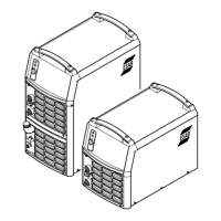
Mig U4000i 6......................................................................
Mig 4000i 7.......................................................................
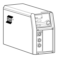
Tig 4000i 8........................................................................
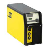
Cooling unit 8....................................................................
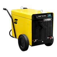
Arc 4000i 9.......................................................................
WIRING DIAGRAM 10.................................................................
Component description 10..........................................................
MMC option for MIG machines 13...................................................
Mig U4000i valid for serial number 803--xxx--xxxx 14..................................
Mig 4000i valid for serial number 803--xxx--xxxx 16...................................
Tig 4000i valid for serial number 803--xxx--xxxx 18....................................
Arc 4000i valid for serial number 803--xxx--xxxx 20...................................
DESCRIPTION OF OPERATION 22.....................................................
AP2 Interference suppressor board 22...............................................
1 MMC module 22..................................................................
2AP1 Interference suppressor board (EMC board) 23.................................
5 Cooling unit 24...................................................................
15 The power module 25............................................................
15AP1 Power board 26.............................................................
15AP1:1 Mains rectifier bridge and charging circuit 26..................................
15AP1:2 Switching circuit 27........................................................
15AP1:3 Overvoltage and undervoltage protection 27...................................
15AP1 Component positions 28....................................................
15AP2 Gate driver board 29.........................................................
15AP2:1 Gate driver stages 29......................................................
15AP2:2 Overvoltage and undervoltage protection 30...................................
15AP2 Component positions 31....................................................
20AP1 Control board 32............................................................
20AP1:1 Power supply 32...........................................................
20AP1:2 Fan control 33.............................................................
20AP1:3 The CAN bus 34...........................................................
Starting sequence 35.......................................................
Communication interruptions 35.............................................
Terminating resistors 35....................................................
20AP1:4 Temperature monitoring 36..................................................
20AP1:5 Overvoltage and undervoltage protection 36...................................
20AP1:6 Communication with relay board 20AP2 37....................................
20AP1:7 Gate pulses 37............................................................
20AP1:8 Current sensor 37.........................................................
20AP1:9 Arc voltage feedback for Universal and MIG machines 38.......................
20AP1:9 Arc voltage feedback for TIG and MMA machines 40...........................
20AP1 Component positions 41....................................................
20AP2 Relay board 42..............................................................
20AP2:1 Power supply 42...........................................................
20AP2:2 External shutdown 42......................................................
20AP2:3 Starting sequence 43.......................................................
20AP2:4 Power supply to the cooling unit 44..........................................
20AP2:5 Cooling water monitoring in MIG welding mode 44.............................
20AP2:5 Cooling water monitoring in TIG welding mode 46..............................
20AP2:6 TIG Gas valve 47..........................................................
20AP2:7 TIG HF starting device 47...................................................
20AP2:8 TIG Starting 47............................................................
20AP2:9 Gas flow monitor 48........................................................
20AP2 Component positions 48....................................................
20AP2 Circuit diagram 49.........................................................




 To Next Page