SECTION 6 Troubleshooting
ESP 400C and 600C Plasma Power Sources
6-3
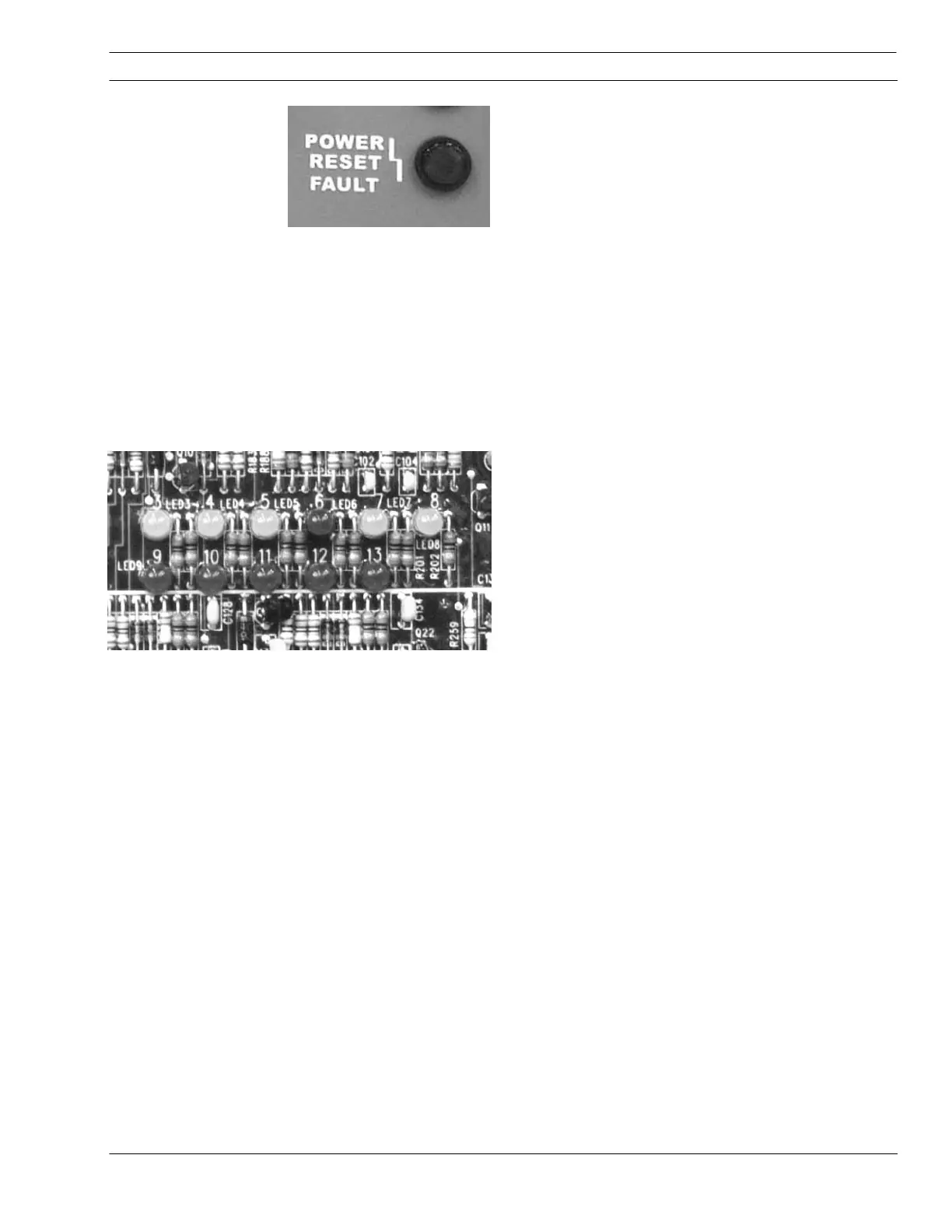
Power Reset Fault Indicator (on front panel)
Illuminates when a serious fault is detected. Input
power must be disconnected for a least 5 seconds
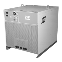
to clear this fault. Check PCB1 Red LEDs 6, 9, 10,
11, 12, and 13 if this fault is illuminated for further
diagnosis.
LED 6 – (red) Right Overcurrent Fault –
Illuminates when the current out of the right side
chopper is too high (300 amps). This current is
measured by the right-side hall sensor. The power
source is shut down.
LED 9 – (red) Left Overcurrent Fault –
Illuminates when the current from the left side
chopper is too high (300 amps). Measured by the
left hall sensor. Power source is shut down.
LED 10 _ (red) Left IGBT Unsaturated Fault –
Illuminates when left IGBT is not fully conducting.
PS (PS) is shut down.
LED 11 – (red) Right IGBT Unsaturated Fault –
Illuminates when right IGBT is not fully conducting.
Power Source (PS) is shut down.
LED 12 – (red) Left -(neg) 12V Bias Supply
Fault – Illuminates when negative 12 V bias supply
to the left side IGBT gate drive circuit (located on
PWM-drive board PCB2) is missing. PS is shut
down.
LED 13 – (red) Right –(neg) 12V Bias Supply
Fault - Illuminates when negative 12 V bias supply
to the right side IGBT gate drive circuit (located on
PWM-drive board PCB3) is missing. PS is shut
down.