SECTION 3 Installation
ESP-400C Plasma Power Source
3-9
System Interconnecting Block Diagram with Smart Flow II
1
3 phase with ground (wall disconnect)
2
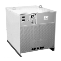
Front view
3
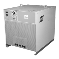
Rear view
4
Remote to CNC
5
CNC
6
CNC Input/Output to Smart Flow II
7
Torch Lead (-)
8
Pilot Arc Lead
9
Work Lead (+)
10
SmartFlow II
11
Cut Water Pump (required for PT-15)
12
Cooling Water to Torch
13
Cooling Water from Torch
14
Voltage Height Control
15
Plasma Torch Lead Bundle and Torch
16
Earth Ground
17
On/Off Control
18
WC-7C Water Cooling