6 BASIC WELDING GUIDE
0463 815 001 - 51 - © ESAB AB 2021
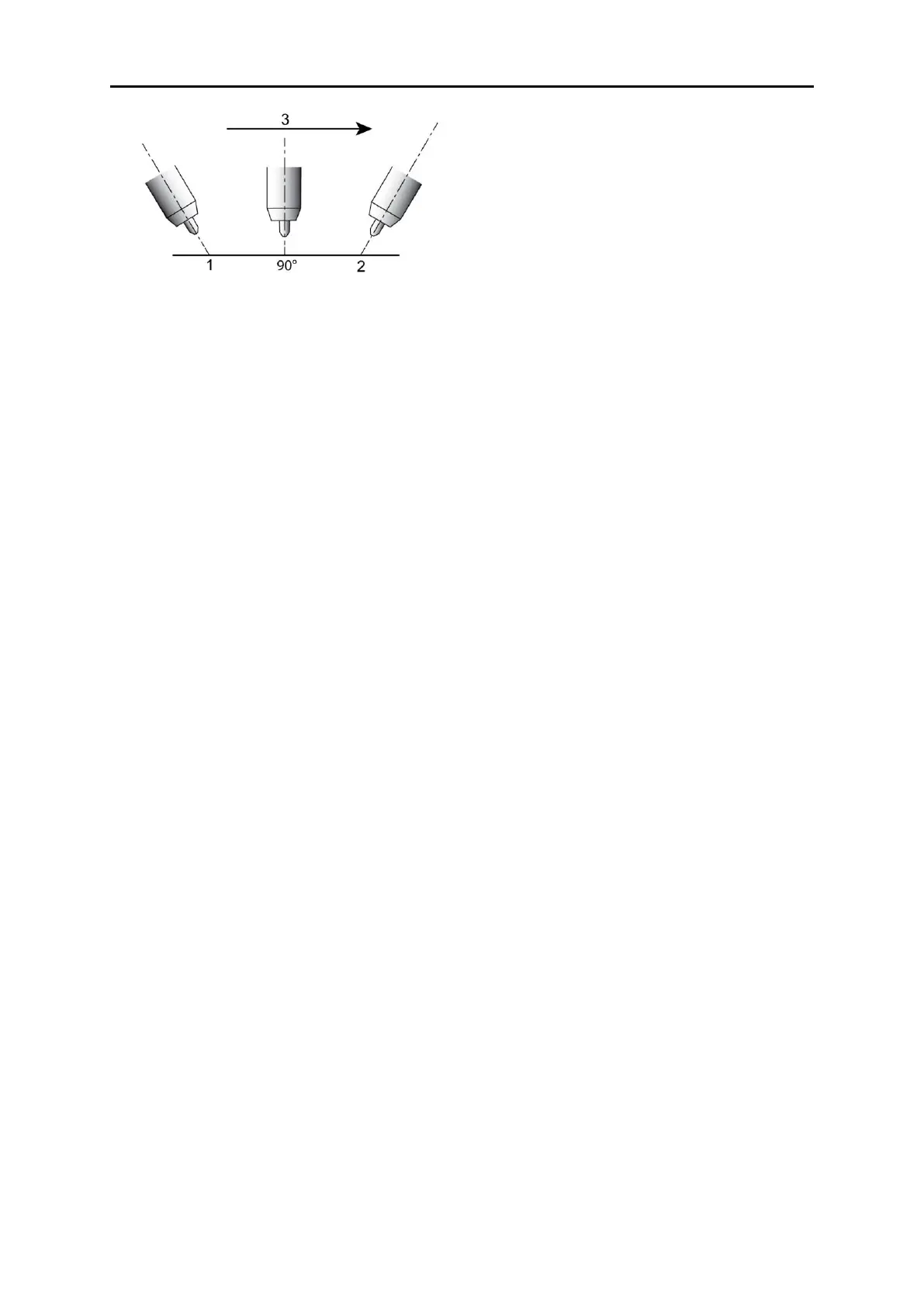
Figure 47: Nozzle angle, right handed operator
1 Leading or “pushing” angle (forward pointing) 3 Direction of torch travel
2 Trailing or “pulling” angle (backward pointing)
Establishing the arc and making weld beads
Before attempting to weld on a finished piece of work, it is recommended that practice welds be
made on a sample metal of the same material as that of the finished piece.
The easiest welding procedure for the beginner to experiment with MIG welding is the flat
position. The equipment is capable of flat, vertical and overhead positions.
For practicing MIG welding, secure some pieces of 1/16 in. or 3/16 in. (1.6 mm or 5.0 mm) mild
steel plate 6 in. × 6 in. (150 mm × 150 mm). Use .035 in. (0.9 mm) flux cored gasless wire or a
solid wire with shielding gas.
Power source setting
Power source setting requires some practice by the operator, as the welding plant has two control
settings that have to balance. These are the wire speed control (see "Firepower regulator"
section) and the welding voltage control, see " Firepower MST-200, Firepower FP-200 controls,
indicators and features" section. The welding current is determined by the wire speed control, the
current will increase with increased wire speed, resulting in a shorter arc. Less wire speed will
reduce the current and lengthen the arc. Increasing the welding voltage hardly alters the current
level, but lengthens the arc. By decreasing the voltage, a shorter arc is obtained with a little
change in current level.
When changing to a different electrode wire diameter, different control settings are required. A
thinner electrode wire needs more wire speed to achieve the same current level.
A satisfactory weld cannot be obtained if the wire speed and voltage settings are not adjusted to
suit the electrode wire diameter and the dimensions of the workpiece.
If the wire speed is too high for the welding voltage, “stubbing” will occur as the wire dips into the
molten pool and does not melt. Welding in these conditions normally produces a poor weld due to
lack of fusion. If, however, the welding voltage is too high, large drops will form on the end of the
wire, causing spatter. The correct setting of voltage and wire speed can be seen in the shape of
the weld deposit and heard by a smooth regular arc sound. Refer to the Weld Guide located on
the inside of the wirefeed compartment door for setup information.
Electrode wire size selection
The choice of Electrode wire size and shielding gas used depends on the following:
• Thickness of the metal to be welded
• Capacity of the wire feed unit and power source
• The amount of penetration required
• The deposition rate required
• The bead profile desired
• The position of welding
• Cost of the wire

 Loading...