Do you have a question about the ESAB fabricator 211i and is the answer not in the manual?
Core safety guidelines for operating welding and plasma cutting equipment.
Table of technical specifications for the ESAB Fabricator 211i.
Details on voltage requirements, earthing, and power cord connections.
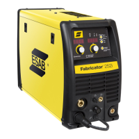
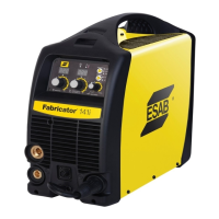
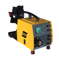
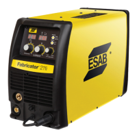
Overview of front and rear panel controls, indicators, and connections.
Configuration steps for MIG welding with gas shielded wire.
Configuration steps for MIG welding with flux core (gasless) wire.
Configuration steps for Spool Gun MIG welding.
Configuration steps for Lift TIG welding.
Configuration steps for Stick welding.
Table of common faults, possible causes, and remedies for the power source.
Schedule and procedures for regular maintenance and calibration.
Pre-power-on checks and safety warnings before internal inspection.
Procedures for calibrating output voltage, current, and wire speed.
Safety warnings and precautions before starting disassembly procedures.
Step-by-step instructions for removing the Control PCB.
Instructions for removing the front panel assembly.
Step-by-step instructions for removing the Display PCB.
Instructions for reinstalling the front panel.
Steps for installing the control PCB and associated cover.
| Input Voltage | 120/230 VAC |
|---|---|
| Input Phase | Single Phase |
| Rated Output at 230 VAC | 210 A |
| Processes | MIG, Stick, TIG |
| Wire Size Range | 0.6-0.9 mm (0.023-0.035 in) |