ESAB FABRICATOR 211i
Manual 0-5450 5-5 TROUBLESHOOTING
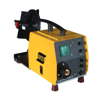
5.04 Test Equipment and Tools Needed for Troubleshooting and Servicing
Art # A-09849
• DigitalMultimeter
• DCclip-onammeter
• Screwdriverandspanner
• Oscilloscope&isolatingtransformer
5.05 Visually Inspect
Visually inspect the inside of the Power Source. The levels of current present in these units can cause burning or arcing of PCB, trans-
formers, switches, or rectifier when a failure occurs. Carefully inspect all components within these units.
Look in particular for the following:
a) Loose or broken wires or connectors.
b) Burned or scorched parts or wires or evidence of arcing.
c) Any accumulation of metal dust or filings that may have caused shorting or arcing.
If any parts are damaged, they must be replaced. Refer to the Spare Parts section for a complete list of components used in the Power
Source.
Locate the faulty component(s) then replace where necessary.
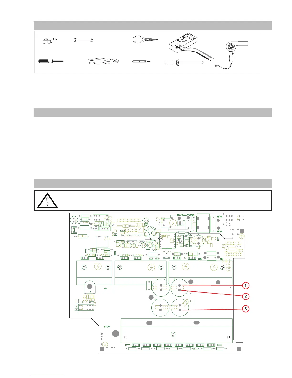
5.06 Preliminary DC Bus Measurement of the Power PCB
!
WARNING
Check DC bus voltage has discharged to less than 5VDC before servicing. Ensure the mains supply plug is
disconnected from receptacle.
 Loading...