23
3.0 INSTALLATION
3.1 LOCATION
Several factors should be considered when selecting an in-
stallation site. Adequate ventilation is necessary to provide
cooling, and the amount of dirt and dust to which the machine
is exposed should be minimized. There should be at least 18
inches of unrestricted space between the machine’s side and
rear panels and the nearest obstruction to provide freedom
of air movement through the power source.
3.2 HANDLE ASSEMBLY INSTALLATION
The Multimaster 300/300X is factory assembled except for
the front handle assembly which is mounted to the machine
upside down for shipping purposes. The handle assembly
consists of two brackets and a cross bar. To install the handle
in its proper position, do the following:
A. Remove the two sheet metal screws from the brackets on
each side of the front handle assembly. See Figure 3A.
B. Remove front handle assembly and reverse sides with the
mounting brackets. This will put the handle assembly in
the proper orientation. Reattach brackets using the sheet
metal screws removed in Step A. See Figure 3B.
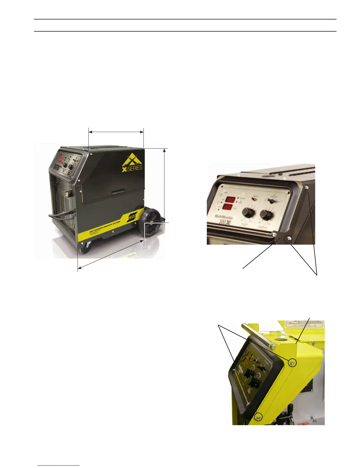
Figure 2 - Dimensions
Sheet metal Screws
The installation site should permit easy removal of the ma-
chine’s outer enclosure for maintenance. Installing or placing
any type of ltering device will restrict the volume of intake
air, thus subjecting the internal components to overheating.
Warranty is void if any type of ltering device is used.
Figure 3B - Handle Assembly Installation
SECTION 3 INSTALLATION
Sheet metal
Screws
Figure 3A - Handle Assembly Removal
Handle Bracket
Handle Bracket
20”
32”
42”