Do you have a question about the ESAB Origo Mig 510 and is the answer not in the manual?
Familiarity with operation, precautions, workplace suitability, and fire safety.
Operator duties, unauthorized persons, and required PPE.
Warnings for electric shock, fumes, arc rays, fire, and noise hazards.
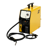
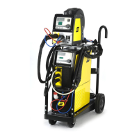
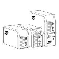
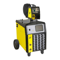
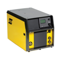
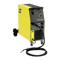
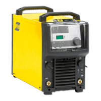
Description of Mig 410/510 power sources, cooling, and instrument display.
Lists items included with the power source, like cables and manuals.
Position the welding power source to ensure unobstructed cooling air flow.
Steps for assembling components and ensuring correct wheel orientation.
Instructions for assembling the stabiliser and CB KIT for counter balance.
Details on electrical connection and mains power supply requirements.
Connecting to the correct mains voltage and ensuring protective earth.
Identifies and describes the various connection and control elements on the unit.
Procedure for starting the power source and its idle mode.
Explains the 2-step fan control and automatic shutdown for overheating.
Details on connecting water hoses and the function of the ELP sensor.
How the water flow guard prevents welding if coolant flow is interrupted.
Describes the unit's automatic switch to idle mode after inactivity.
Explains the effect of inductance on weld quality and spatter.
Guidance on regular inspection, cleaning power source/gun, and topping up coolant.
Steps for identifying and resolving common operational faults.
Instructions on how to order genuine ESAB spare and wear parts.
Main electrical schematic for the Mig 410 power source.
Electrical schematic for the Mig 410 with 230-500V configuration.
Electrical schematic for the Mig 510 with 400-415V configuration.
Electrical schematic for the Mig 510 with 230-500V configuration.
Diagrams detailing connections to various terminals and components.
Lists wire feeders, digital meters, CO2 heater kit, and water flow guard.
Details connection sets for different models and the counter balance stabiliser kit.
| Brand | ESAB |
|---|---|
| Model | Origo Mig 510 |
| Category | Welding System |
| Language | English |