Do you have a question about the ESAB Origo Mig L3000i and is the answer not in the manual?
Explains the transistor-controlled inverter principle and the function of various modules within the power source.
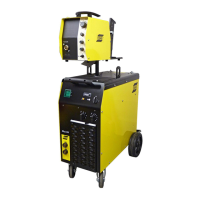
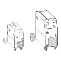
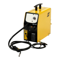
Provides key specifications for Mig L3000i and Mig C3000i models, including voltage, current, and duty cycle.
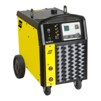
Details technical specifications for Tig 3000i and Tig 3000i AC/DC models, covering mains voltage, current, and load limits.
Lists and describes the various components used within the wiring diagrams, including modules and connectors.
Presents the wiring schematic specific to the Mig L3000i welding machine.
Illustrates the wiring schematics for Mig C3000i, covering different serial number ranges.
Shows the wiring schematic for the Tig 3000i welding machine.
Details the wiring schematic for the Tig 3000i AC/DC welding machine.
Explains the function of the MMC module, including control panel and welding data board interaction.
Describes the 2AP1 board for interference suppression and the main rectifier 2BR1.
Details the functions of the 10AP1 TIG board, including power supply, gas valve, and HF generator.
Explains the operation and identity of the 13AP1 wire feeder control board.
Describes the power module, its dual forward inverter design, and heat sink components.
Covers the functions of the 15AP1 power board, including charging, gate driver, and protection circuits.
Details the 15AP2 secondary board, its diode modules, and temperature monitoring.
Explains the operation of the 18AP1 AC control board, monitoring temperature and controlling fans.
Describes the 18AP2 AC power board, focusing on its switching circuits and IGBT modules.
Details the operation of the 20AP1 control board, its role in monitoring and controlling the power source.
Explains the setup and use of the CAN adapter option for the Mig C3000i.
Describes how faults are logged and displayed, including unit numbers for fault identification.
Provides a table summarizing fault codes and the units they affect.
Details specific fault codes for Power Source, AC Unit, and Wire Feed Unit, including causes and actions.
Provides essential information about Electrostatic Discharge (ESD) and how to prevent component damage.
Introduces service tools and the ESAT service kit for software updates and diagnostics.
Describes special tools like the soft-starting tool SST 2 used for service procedures.
Guides on how to check the power board 15AP1, including resistance and voltage measurements.
Provides instructions for checking the secondary board 15AP2, including diode and NTC resistor checks.
Details procedures for checking IGBT modules on the AC power board 18AP2.
Explains how to measure gate voltages for IGBTs on the AC power board 18AP2.
Outlines the soft starting procedure for power modules after component replacement or during fault tracing.
Describes the process for calibrating the current sensor signal using a potentiometer.
Guides on calibrating arc voltage feedback for MIG machines using potentiometers.
Details the calibration of arc voltage feedback for DC TIG machines.
Explains how to calibrate the arc voltage display for AC TIG machines.
| Brand | ESAB |
|---|---|
| Model | Origo Mig L3000i |
| Category | Welding System |
| Language | English |