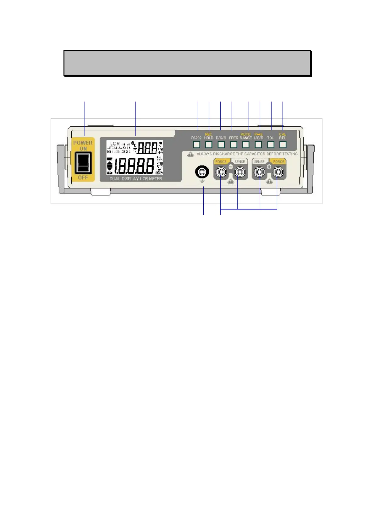
FRONT PANEL ILLUSTRATION
1 2 3 4 5 6 7 8 9 10
11 12
Figure-1. Front panel
1. POWER SWITCH: used to turn the power ON and OFF.
2. LCD display
3. RS232: Press this button to toggle RS232 function On/OFF.
4. HOLD (REC): Press this button to hold data. Press this button for
more than 1 second to enter Static Recording for Maximum,
Minimum and Average reading.
5. D/Q/θ: Press this button to select Dissipation factor, Quality factor
and Phase angle displays.
6. FREQ: Press this button to select test frequency.
7. RANGE (AUTO): Press this button to select measuring range.
Press this button for more than 1 second to set auto range.
8. L/C/R (P-S): Press this button to select Inductance, Capacitance
and Resistance measurements. Press this button for more than
one second to toggle parallel and series mode.
9. TOL: Tolerance mode selection button
10. REL (CAL): Relative mode and Calibration selection button
11. Protective Ground to be connected a plate for preventing noise
influence.
12. Input Terminals.
4