MEASURING L/CR
Inductance/ Capacitance/ Resistance Measurement
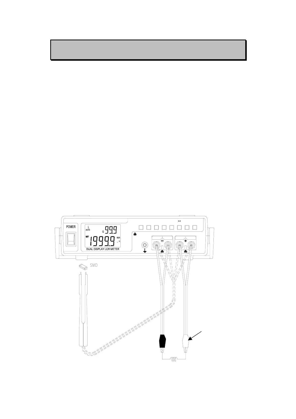
1. Press “L/C/R” button to select inductance (L), capacitance (C) or
resistance (R) measurement.
2. Connect the BNC ends of red clip or SMD Tweezers to “SENSE +”
and “FORCE +”, respectively.
3. Connect the BNC ends of black clip or SMD Tweezers to “SENSE
-” and “FORCE -”, respectively.
4. Connect the test clips to the component leads as required or using
SMD Tweezers to measure SMD component.
5. Press “FREQ” button to select testing frequency.
6. Press “D/Q/θ” button to select Q or D factor for secondary display
as necessary.
7. Remove your hands from clips then read the display readings.
8. Please refer to Figure-4~6 for inductance, capacitance and
resistance measurement.
u
FORCE SENSE
ON
OFF
SENSE FORCE
ALWAYS DISCHARGE THE CAPACITOR BEFORE TESTING
REC
HOLDRS232 D/Q/
P SAUTO
RANGEFREQ L/C/R
CAL
REL
θ
TOL
Red clip
Figure-4. Inductance Measurement
8