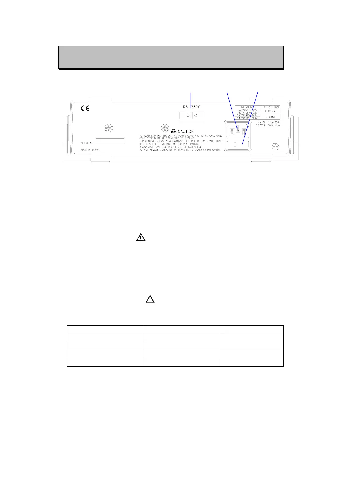
REAR PANEL ILLUSTRATION
1 2 3
Figure-2. Rear Panel.
1. Optical RS-232 interface port.
2. Power cord socket.
3. Line voltage selector and fuse holder: to select line voltage and fuse
replacement.
CAUTIONS
In order to avoid damaging this instrument, make sure that the unit is
set to the correct line voltage for your area. Also make sure that the
correct fuse is used for the line voltage. These line voltages are 100V,
120V, 220V and 240V at 50/60HZ.
WARNING
To avoid damage the equipment use only specified fuse when change
the power line voltage. Please refer to following table
SELECTOR LINE VOLTAGE FUSE 5x20mm
100V 90~110V 50/60Hz
120V 108~132V 50/60Hz
T 125mA
220V 198~242V 50/60Hz
240V 216~264V 50/60Hz
T 63mA
Although this instrument is protected against reverse polarity damage
the circuit being powered may not include such protection. Always
carefully observe polarity incorrect polarity may damage the equipment
under test. Do not exceed the voltage rating of the circuit being powered.
5