4 / 8 P/N P-047550-1726-EN • REV 08 • ISS 05AUG16
• Polarity at terminals is shown in the supervisory condition.
Connect as shown in the diagram. (Polarity reverses on
alarm.)
• IDC wiring is Style B (Class B) or Style D (Class A).
To wire the module:
1. Verify that all field wiring is free of opens, shorts, and
ground faults.
2. Strip 1/4 in. (about 6 mm) from the ends of all wires that
connect to the terminal block of the module.
When stripping wire ends, exposing more wire may cause
a ground fault; exposing less wire may result in a faulty
connection.
3. Make all wiring connections using the appropriate figure
below for the desired function (personality code). See
Figure 3 to Figure 7.
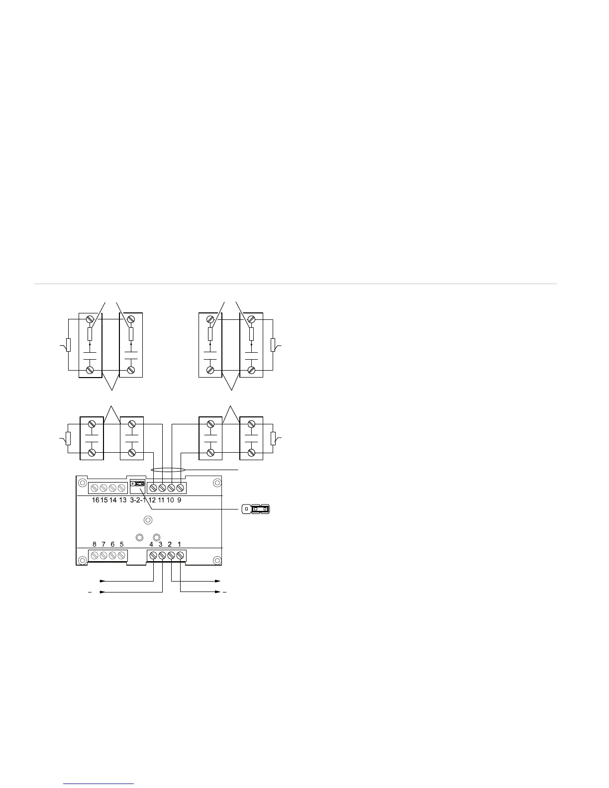
Figure 3: Class B initiating device circuit (personality codes 1, 2, 3, 4, 18)
(1) 47 kΩ EOL resistor (PN EOL-47) used for Class B only
(2) For personality code 18, use a 22 kΩ resistor
(3) Input 2: Typical NO initiating device
(4) Input 1: Typical NO initiating device
(5) 10 VDC at 350 µA max.
(6) Signaling line circuit (SLC) to next device
(7) Signaling line circuit (SLC) from previous device, power-limited
and supervised
321
JP1
(5)
+
(6)
+
(7)
(1)
(1)
(4)
(1
(1
(2)
2
(3)
 Loading...
