P/N P-047550-1726-EN • REV 08 • ISS 05AUG16 5 / 8
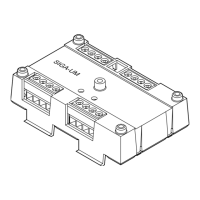
Figure 4: Form C dry contact relay (personality code 8)
(1) SIGA-UM must be installed in the same room as the device it
controls
(2) Power-limited unless connected to a nonpower-limited source. If
the source is nonpower-limited, eliminate the power-limited mark
and maintain a minimum of 0.25 in. (6.4 mm) space from power-
limited wiring. For other mounting methods, see enclosure and
bracket installation sheets to maintain separation of power-
limited and nonpower-limited wiring. The wire size must be
capable of handling fault current from nonpower-limited source.
— or —
Use type FPL, FPLR, FPLP, or permitted substitute cables,
provided these power-limited cable conductors extending
beyond the jacket are separated by a minimum of 0.25 in.
(6.4 mm) space or by a nonconductive sleeve or nonconductive
barrier from all other conductors. Refer to the NFPA 70 National
Electrical Code for more details.
(3) The relay function is programmable
(4) Normally open
(5) Normally closed
(6) Common
(7) Signaling line circuit (SLC) to next device
(8) Signaling line circuit (SLC) from previous device, power-limited
and supervised
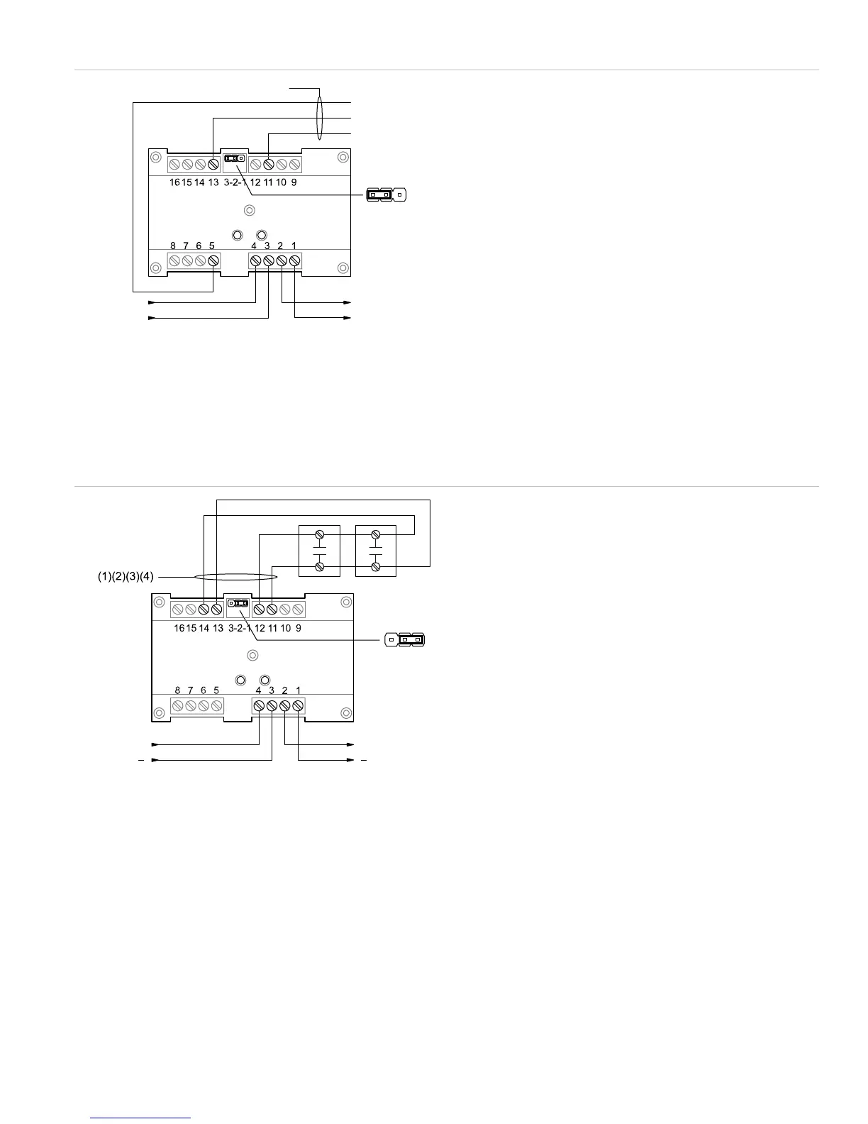
Figure 5: Class A initiating device circuit (personality codes 9, 10, 11, 12)
(1) Input 1: Typical NO initiating device
(2) 10 VDC at 350 µA max.
(3) Maximum 12.5 Ω resistance per wire for Class A configurations.
(4) Supervised and power-limited unless connected to a nonpower-
limited source. If the source is nonpower-limited, eliminate the
power-limited mark and maintain a minimum of 0.25 in.
(6.4 mm) space from power-limited wiring. For other mounting
methods, see enclosure and bracket installation sheets to
maintain separation of power-limited and nonpower-limited
wiring. The wire size must be capable of handling fault current
from nonpower-limited source.
— or —
Use type FPL, FPLR, FPLP, or permitted substitute cables,
provided these power-limited cable conductors extending
beyond the jacket are separated by a minimum of 0.25 in.
(6.4 mm) space or by a nonconductive sleeve or nonconductive
barrier from all other conductors. Refer to the NFPA 70 National
Electrical Code for more details.
(5) Signaling line circuit (SLC) to next device
(6) Signaling line circuit (SLC) from previous device, power-limited
and supervised
++
NO
NC
C
321
JP
(1)(2)(3)
(7)(8)
(4)
(6)
(5)
21
JP1
3
+
(5)
+
(6)
 Loading...
