WARNINGS
• Do not expose to wet and humid conditions and avoid
mechanical force or pressure on the decoder.
• Do not remove the heat shrink sleeve.
• Never solder on the board, extend cables if necessary.
• Never wrap the decoder in insulation tape, since this may
cause overheating.
• Any wiring has to be carried out while power is discon-
nected.
• Make sure that neither the decoder nor any blank wire
ends may come into contact with the engine chassis (risk
of short circuit).
• Never operate the LokPilot unattended.
Requirements for Installation
The locomotive must be in perfect operating condition
prior to the conversion: Only a locomotive with faultless
mechanical properties and smooth running characteristics
in analogue mode is worth converting to digital. Check
and replace all wear and tear parts such as motor brushes,
wheel contacts, light bulbs etc., if necessary.
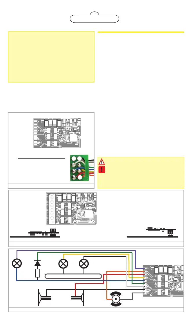
Figure 3: Wiring diagram for LokPilot 5 Basic (wiring example)
violet
orange
red
yellow
blue
green
white
black
gray
R
locomotive chassis
violet
AUX2
green
AUX1
yellow
Rear
light
black
orange
gray
red
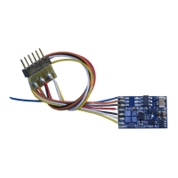
Figure 1: LokPilot 5 Basic with 8-pin interface
Pin Description Color
1 Right motor terminal orange
2 Rear light yellow
3 Output AUX1 green
4 Left track terminal black
5 left motor terminal gray
6 Head light white
7 Common (U+) pole blue
8 Right track terminal red
5 4
1
AUX2 --
Right motor terminal --
right track terminal --
Rear Light --
U+ (positive Pole) --
AUX1 --
Head light --
Left track terminal --
Left motor terminal --
-- GND
-- AUX9
-- U+
AUX9 is a logik level output. Default: PwrPackCtrl
Back
Figure 2: LokPilot 5 Basic with 21MTC interface
AUX10 1
AUX7 2
AUX6 3
AUX4 4
SUSI(AUX12) 5
SUSI(AUX11) 6
Rear light 7
Head light 8
n.c. 9
n.c.10
Index pin 11
22 Right track
21 Left track
20 GND
19 Right motor
18 Left motor
17 AUX5
16 U+ (+ Pole)
15 AUX1(Power)
14 AUX2(Power)
13 AUX3
12 VCC
How to connect the decoder:
Insert the decoders with
connector towards up
(e.g. Atlas®, Intermoun-
tain, Bowser, Märklin®)
Locomotive PCB
(Side view)
Locomotive PCB
(Side view)
-- GND
-- AUX9
-- U+
AUX3, AUX4, AUX5, AUX6, AUX7, AUX10 at the
21MTC interface are logic level outputs
AUX11 is a logic level output or SUSI Clk
AUX12 is a logic level output or SUSI Dta
AUX9 is a logic level output.
Default: PwrPackCtrl for PowerPack
Insert the decoder with
Connector towards
bottom
(e.g. Brawa®, Accurascale)
Installing the Decoder
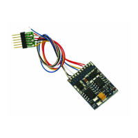
Locomotives with 8-pin NEM 652 interface
Some LokPilot 5 decoders are supplied with an 8-pin in-
terface (refer to Fig 1). Remove the dummy plug from the
socket. Insert the plug of the decoder in such a way that
pin 1 of the plug (this is the side with the red / orange
wires) sits next to the corner of the socket that is usually
marked with *, +, • or 1.
Locomotives with 21MTC interface
Some LokPilot 5 Basic decoders are equipped with an
21MTC interface (fig. 2) You can insert the decoder in
two ways: either the pins are put through the decoder;
the socket of the decoder remains visible after installati-
on (mounting on top) or the decoder is inserted in such a
way that the pins go straight into the socket. Which of the
two mounting positions is the correct one depends solely
on the locomotive. The position of the marker-pin is the
crucial indicator.
Plug the decoder into the socket in such a way that the
locomotive interface corresponds with the decoder. Do
not apply too much pressure when inserting the plug. The
decoder must go in without force.
Locomotives without interface
Firstly, please cut all wires installed in the locomotive. Take
special care to remove any connections to the chassis
(ground): the motor leads must be positively potential-
freemay not have any contact to the chassis or the wheels
and wheel contacts. Figure 3 shows all connections.
Function outputs
You can wire all kind of loads to the function outputs.
Please make sure that the load does not exceed
the permitted maximum current and there are no
short circuits. The outputs of the LokPilot have pro-
tection but if an external voltage is applied, the
outputs may suffer damage or destruction.
white
Head
light
 Loading...