Only install bulbs rated 16V or higher and with a nominal
current draw, that does not exceed 50 mA or use suitab-
le smoke units such as Seuthe No. 11. If you like to use
LEDs, a resistor with a rating between 470 Ohms and 2.2
kOhms need to be wired in series. Running the LED wit-
hout resistor will lead to their immediate destruction! All
function outputs from AUX3 and higher are following the
NEM660-Standard (VHDM RCN-121, NMRA S.9.1.1.3) are
are so called logic level outputs. It is not possible to con-
nect any external load to such outputs directly. External
power transistors are required. Usually, these are already
installed on the locomotive›s motherboard (if required).
For do it your self projects, ESU is offering appropriate ad-
apter boards (e.g.items 51957 or 51968) with transistors.
SUSI/Logic level-outputs
Alternatively, the two pins on the LokPilot 5 Basic with
21MTC interface that are assigned to the SUSI serial in-
terface can also be configured as logic level outputs. In
this way, the number of available outputs can be increased
by two.
Please remember that the two SUSI-pins, available
on 21MTC, Next18 or PluX can be used as logic le-
vel outputs or Servo control lines alternatively, still
following the standards. You have to check the ac-
tual connection of your locomotive motherboard
to be sure about the function.
Connecting capacitors
On many older locomotives, the current pickup is not
very reliable. Therefore, power interruptions may cause a
stop or jerky movement when the locomotive travels over
turnouts at low speeds. This can be overcome with buffer
capacitors. The minimum capacity used should be 470uF
/ 25V. Smaller capacitors will not show good results. You
can connect an electrolyctic capacitor following figure 4.
Charging is done trough a 100 Ohms resistor, limiting the
charging current.
The capacitors must be removed or disabled prior
to programming the decoder using the ESU Lok-
Programmer device!
After connecting the PowerPack, you can make the deco-
der switch off after a certain time. CV 113 is responsible
for that. The factory default value of 31 equals to about
1 second. You should set a time between 0.3s and 1s .
For the PowerPack to work, the function output responsib-
le for the charge (AUX9) must be configured to the «Po-
werPackControl» function. Although this should be set up
by default already, you can do this manually also:
Set CV 31 = 16, CV 32 = 0 first.
Then set CV339 = 31.
DCC Operation
The LokPilot 5 Basic works with any DCC system.
Remove any capacitors that are wired into the
track feeders (e.g. ROCO® feeder track). This
could impair the functionality of the decoder.
The address is set to 03 using 28 speed steps .
F1 switches output AUX1
F2 switches output AUX2
F3 switches the switching mode on and off
F4 switches the acceleration and deceleration on/off
F5 switches output AUX3 (if applicable)
F6 switches output AUX4 (if applicable)
F7 switches output AUX5 (if applicable)
F8 switches output AUX6 (if applicable)
DC Operation
The LokPilot 5 Basic are set ex factory to operation on
conventional DC layouts as well. No settings are needed
to be done.
Decoder Settings (Programming)
A list of the most important CV parameters is given later.
These can be changed using any DCC command station. If
your command station supports RailCom®, you can read
CV values on the main.
A list of all decoder parameters can be found in the de-
tailed manual for the LokPilot 5 Basic, which can be down-
loaded from our website www.esu.eu in the «Downloads»
area. The extensive function mapping is also discussed the-
re, and all light functions are explained there, also.
Lenz ABC-Brake Mode
LokPilot 5 Basic supports the ABC braking technique. To
use this function, a group of anti-parallel diodes will be
soldered to one half of the track. The resulting fall of vol-
tage generates an asymmetrical DCC signal that can be
detected by the decoder.
• If you want to stop the decoder no matter in which half
of the track the diodes are set, please set Bit 0 and Bit
1 in CV 27 (CV27=3).
In some operational situations it may happen that the Lok-
Pilot decoder does not detect the ABC braking section.
You can influence the detection sensitivity with the aid of
CV 134. Cange the default value (10) step by step and test
until you achieve the desired result.
Figure 4: 2200mF capacitor at LokPilot 5 Basic
+
-
2200uF
25V
100Ω,1/4 Watts
1N4007
GND
U+
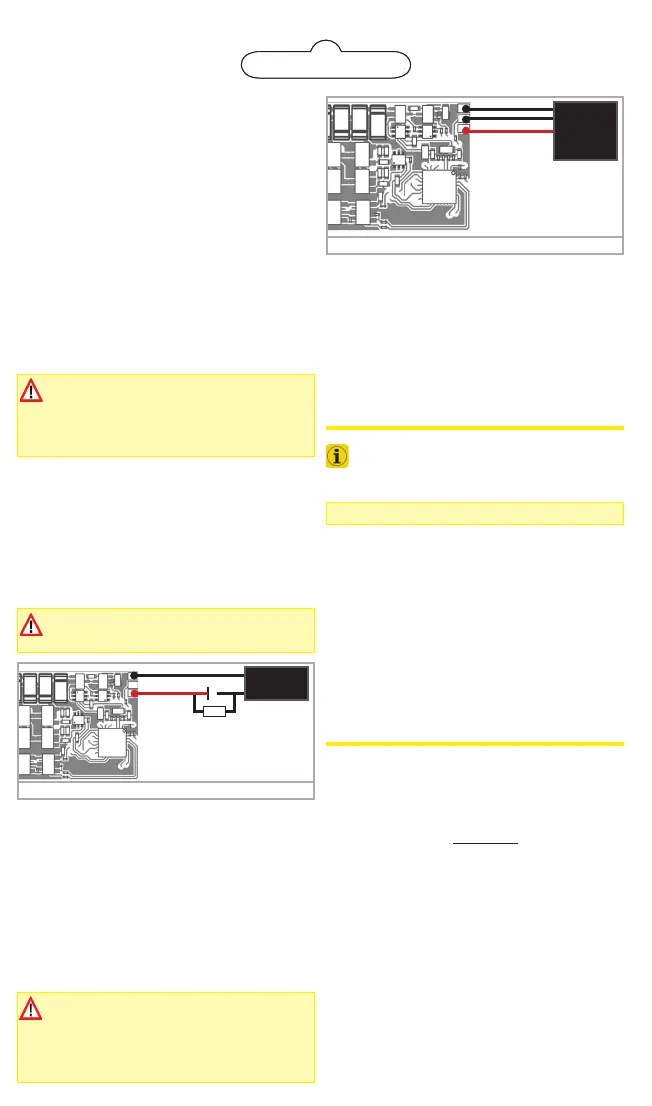
Figure 5: PowerPack at LokPilot 5 Basic
GND
U+
ESU
Power
Pack
Charge
CV 113 buffer time
factory default = 31
(approx 1. second)
PowerPack for LokPilot 5 Basic
You can solder a powerful energy buffer to all LokPilot 5
Basic decoders. The connection diagram figure 5 shows
you how to do it. This «Powerpack» allows your locomo-
tive to keep running for up to 2 seconds without power.
ESU supplies under the item number 54671 or 54672
suitable PowerPack modules. Please do ONLY use these.
• The PowerPack only operates in digital mode. It auto-
matically turns off on analog layouts.
• It may take up to two minutes to fully charge the ca-
pacitor («Goldcap»). Therefore, the time bridged with
the energy buffer depends on the current draw of your
locomotive and the charge-up time.
The time to be bridged with the PowerPack can
be set in CV 113. Output AUX9 needs to be set
to «PowerPackControl» (Should be the default).
 Loading...