EasyManua.ls Logo

Esu SwitchPilot User Manual

Esu SwitchPilot
32 pages
To Next Page IconTo Next Page
Page #1 background imageLoading...
Page #1 background image
1
SwitchPilot
P/N 04708-07029
User manual
Third edition, October 2008
51800 SwitchPilot
51801 SwitchPilot Extension
51802 SwitchPilot Servo

Table of Contents

Question and Answer IconNeed help?

Do you have a question about the Esu SwitchPilot and is the answer not in the manual?

Esu SwitchPilot Specifications

General IconGeneral
ManufacturerEsu
ModelSwitchPilot
CategoryMedia Converter
Power Supply14-24V DC or 16-22V AC
Input Voltage14-24V DC or 16-22V AC

Summary

Features

Connection to the Digital System

6.1. Connecting elements of the SwitchPilot

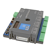
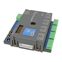
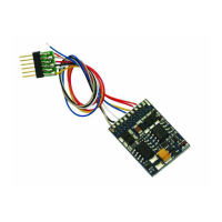
Illustrates and describes the physical connections for the SwitchPilot and Extension.

6.2. Connecting elements of the SwitchPilot Extension

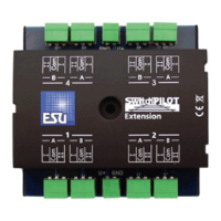
Describes the connection points and functions of the SwitchPilot Extension module.

6.3. Connecting elements of the SwitchPilot Servo

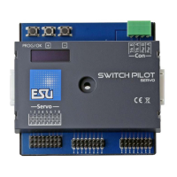
Details the connection points for the SwitchPilot Servo and its optional Extension module.

Wiring of Transistor Outputs

6.7.1. Connecting double-coil solenoids

Guide for wiring double-coil solenoid drives to the SwitchPilot's transistor outputs.

Wiring and Connections

6.8. Wiring a servo

Explains how to connect RC servos to the SwitchPilot and SwitchPilot Servo.

Decoder Settings (Programming)

7.1. Changeable decoder settings

Overview of settings that can be changed via software, distinct from hardware limits.

7.2. Programming with DCC systems

Explains DCC programming methods, including POM and programming track.

Address Settings

8.1. Turnout numbers

Explains how turnouts are numbered and the limits for Motorola and DCC systems.

8.2. Decoder address

Explains how decoder addresses are assigned and stored in CVs.

8.4. Programming addresses with the programming button

Step-by-step guide to programming addresses using the on-board button.

Parameters of the Transistor Outputs

9.1. Configuration of an output with variable duration (k83)

How to configure transistor outputs for variable duration or k83 mode.

9.2. Output configuration to pulsed output with fixed pulse duration

Setting up transistor outputs for fixed duration pulses.

Features of Servo Outputs

10.1. Configuration of servo end position „A“

Setting the 'A' end position for servos via CVs.

10.2. Configuration of servo end position „B“

Setting the 'B' end position for servos via CVs.

10.3. Configuration of servo speed

Adjusting the running time and speed for servo movement between end positions.

RailCom®

Direct Switching with Push Button Inputs

Options for SwitchPilot Extension

Decoder Reset

Technical Data

Related product manuals