23
8) Servo 1 will now continuously move back and forth between
end positions „A“ and „B“.
9) Use the + and – buttons to set the desired turning speed. The
servo will immediately adjust its speed.
10)
Confirm the new speed by pressing the programming
button a)
11) The servo 1 LED turns off and the servo 2 LED lights up which
means that servo 2 can now be configured. Follow steps 3
through 10 again until all servos have been configured.
If you do not want to change a certain value you can simply
confirm it by pressing the programming button and jump to the
next programming step. The configuration changes will be
permanently saved into the appropriate CVs of the SwitchPilot
Servo.
11. RailCom®
RailCom® is a technology which was developed by the company
Lenz Elektronik, Giessen for transmitting information from the
decoder back to the digital control unit. The past DCC system
could only transmit data from the control unit to the decoder but
could never verify whether the data actually arrived or not.
The following information can be sent from the SwitchPilot
decoder to the central unit:
CV Information: The decoder can return all CV values to the
central unit via Railcom®. A programming track will not be
necessary in the future.
11.1. How to activate RailCom®
All SwitchPilot decoders are capable of using Railcom®. It is
disabled by factory default and can be enabled as follows:
Set CV 29 bit 3.
Write the value 6 into CV 28.
The first time the Railcom® function is being enabled it should
be done on the programming track (see sections 7 and 8). After
Railcom® has been turned on you can directly continue with the
other programming steps.
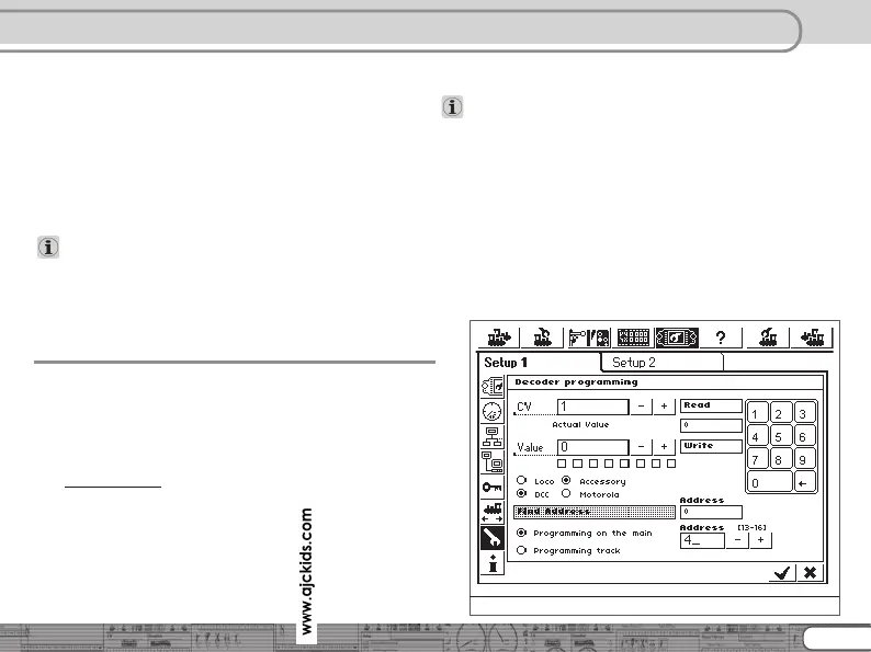
11.2. How to read out CVs with RailCom® and ESU ECoS
After a successful Railcom® activation you can directly read CVs
from the main track – as long as this is being supported by your
central unit. The approach to do this for the ESU ECoS (firmware
1.1.0 or later) is displayed here. In our example a decoder which
is configured for turnout numbers 13 – 16 needs to be read. The
turnout numbers 13 – 16 correspond to decoder address 4. (See
section 8.1)
RailCom
Figure 14: SwitchPilot programming