15
6.10. Polarizing electric frogs
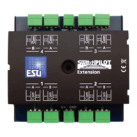
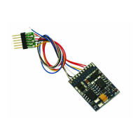
SwitchPilot Extension
You may polarize (supply power of the correct polarity) to the
electro-frog of your turnout (compare figure 9).
If you would like to use a servo with your turnout it is most often
necessary to choose the exact timing in such a way that the relays
only switches when the servo is positioned in the middle between
setting A and B. This way shorts are being prevented. See Chapter
13 for more details.
7. Decoder settings (programming)
Chapter 7 is about changing the settings of the SwitchPilot
decoder. In case you are not familiar with the CVs please take
some time to read through the sometimes very complex
explanations.
After an introduction into the world of parameters in Chapter
7.1, Chapter 7.2 explains how to change the parameters with
different DCC control units.
Chapters 8 through 11 explain which parameters influence the
behavior of the SwitchPilot decoder.
7.1. Changeable decoder settings
Certain capabilities of the SwitchPilot decoder like the amount
of function outputs or the maximum current load are physically
limited through hardware and are not changeable. However, there
are still plenty of possibilities to change the behavior of the
SwitchPilot decoder through software changes.
For each individual parameter there are one or more storage
locations within the decoder in which numbers or letters can be
stored. You can think of these storage locations as index cards
which are kept in a large file cabinet. In order to find the indivi-
dual index cards each one has a number or description with the
property of the card, e.g. „Loco Address“ or „Maximum Speed“.
Now imagine that those cards can be written on with a pencil;
changes are always possible through erasing and writing. Not all
„cards“ can be written on. Certain pieces of information like the
manufacturer identification for ESU are hardcoded.
The content of these storage locations can be chosen by you and
is being read and considered by the decoder. You can fill the
storage locations with any value through a procedure that is also
known as programming.
7.1.1. Configuration Variables (CV)
All SwitchPilot decoders follow the CV concept which was
developed in the United States. The name CV (Configuration
Variable) is derived from the fact that the memory cells being
described above are not only variable but can also configure the
behavior of the decoder.
7.1.1.1. Standardization
The NMRA (National Model Railroad Association) has specified
which CV controls what function in a decoder. The DCC norm
describes the CVs with numbers whereby the most important
ones are given. Thereby the handling of CVs is simplified for the
user since decoders of many manufacturers follow this
standardization and the learned handling of CVs can be applied
everywhere. Within the DCC CV concept number values between
0 and 255 can be written into CVs. Each CV consists of exactly
one number. While the position (CV number) has been
predetermined the actual range of values can vary. Not all CVs
need to accept values between 0 and 255. Allowed values for
the SwitchPilot decoder are shown in the list in Chapter 16.
Decoder settings (programming)