10
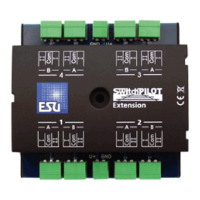
6.3. Connecting elements of the SwitchPilot Extension
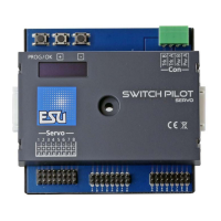
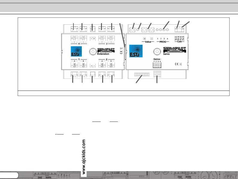
Figure 2 shows the SwitchPilot Servo with its optional SwitchPilot
Extension module.
c) The power supply for the SwitchPilot and all the devices
connected to it are wired to the terminals
Pw A und Pw B.
Both AC- and DC power supplies as well as the digital track
voltage can be used.
d) The screw terminals
Trk A and Trk B connect the SwitchPilot
with the power output of a command station (e.g. booster
output) transmitting the digital commands.
f) The LED in conjunction with the
g) programming button helps you to set the digital address of
the SwitchPilot. This process is described in chapter 8. In
addition, using the programming button or
k) Input unit with a „+“ and „-“ buttons and monitor LEDs 1)
directly Servo end positions „A“ and „B“ and the rotation
speed set.
l) Monitor LEDs. During the setup of Servo end position and
rotational speed on the input unit actively and show what
servo is being edited. For more information about programming
with the input unit, see section 10.4.
m) This pin block serves to connect up to 8 external push buttons
or toggle switches to operate the servo positions directly
without digital control unit. Chapter 12 gives details.
n) This pin block serves to connect four RC servo motors (eg
ESU, Graupner®, Futaba®, etc.) and forms the outputs 1-4 of
the SwitchPilot servo.
h) Extension connector (female / male): Here is the connection
between SwitchPilot Servo and SwitchPilot Extension unit.
Connecting elements of SwitchPilot Servo
Figure 2: SwitchPilot connected with SwitchPilot Extension
m)
n)
c)
l)
f)
g)
d)
i)i)i)i)
i)i)i)i) h)
j)
j)
k)