Do you have a question about the Esu SwitchPilot 3 Plus and is the answer not in the manual?
Overview of the SwitchPilot 3 Plus capabilities, including output types and power sources.
Details on input voltage, outputs, output power, feedback, modes, configuration, and dimensions.
Lists the items included in the SwitchPilot 3 Plus package and available accessories.
Describes the pulse operation mode, ideal for solenoid turnout drives.
Details the PECO mode for optimal control of PECO drives, with enhanced current for peak needs.
Explains K83 mode for turnout drives with end position shutdown or uncoupling tracks.
Describes K84 mode for bistable continuous operation, suitable for lighting and signals.
Details the alternating flasher mode for illuminating St. Andrew's crosses.
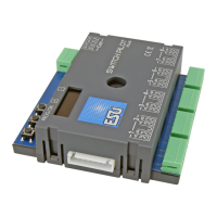
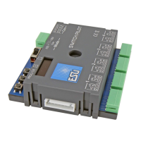
Identifies and describes all terminals on the SwitchPilot 3 Plus for connecting accessories and power.
Explains how to power the SwitchPilot 3 Plus directly from the digital system's track output.
Recommends using an external power supply for larger layouts and details requirements.
Provides wiring instructions for connecting solenoid turnout drives to the outputs.
Details wiring for daylight signals with lamps or LEDs, requiring K84 mode.
Explains wiring for uncoupling tracks using momentary action mode.
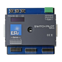
Details the connection and functionality of relay outputs on the extension module.
Explains how to control motorized turnout drives using the extension module.
Shows the wiring for LGB® turnout drives and their operation.
Describes how to set turnout frog polarization using the SwitchPilot Extension Module.
Explains how accessory addresses and turnout numbers are assigned and linked.
Provides a step-by-step guide to assigning turnout numbers directly on the SwitchPilot 3 Plus.
Details the use of the OLED display and buttons for navigating and configuring the decoder.
Explains how to set the address mode for compatibility with ROCO® command stations.
Describes how to individually configure each output's mode, time, and zoom settings.
Details how to set fade-in and fade-out times for smooth lighting effects.
Explains how to view the decoder's hardware/software versions and supply voltage.
Describes how to interpret the output state information shown on the display.
Explains that no special connections are needed for POM configuration.
Guides on how to read and write CVs using POM via the command station.
Details the wiring required for configuring via the programming track.
Guides on reading and writing CVs using the programming track.
Details how to enable or disable RailCom® functionality on the SwitchPilot 3.
Describes the procedure for resetting the decoder using the programming button.
Explains how to reset the decoder by writing a specific value to CV 8.
Details how to perform a decoder reset directly using the device's display.
| DCC Compatibility | Yes |
|---|---|
| Motorola Compatibility | Yes |
| Servo Control | Yes |
| Updateable | Yes, via ESU LokProgrammer |
| Connector Type | Screw terminals |
| Control Type | DCC, Motorola |
| Protection | Short circuit and overload protection |