18
OUTPUT1
Mode : AltFlash
Time : 1720 ms
Zoom : Disabled
Introduction to the operating structure
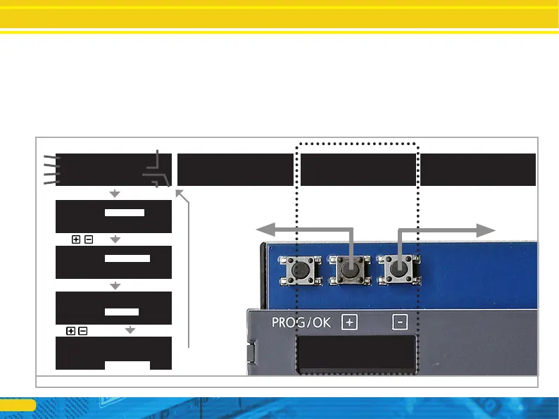
6.2. Introduction to the operating structure
The configuration with the aid of the OLED display and the 3-but-
ton input unit enables you to set all parameters of the SwitchPilot
3 Plus decoder.
All properties are arranged in so-called „panels”. A panel fills in
all four lines of the display. The first line displays the name of the
panel, and rows two to four display a maximum of three different
setting options. With the help of the „+” and „-” buttons you can
scroll between the individual panels.
a) Name of the panel
b) Name of setting option 1
c) Value of the setting option 1
d) Name of setting option 2
e) Value of the setting option 2
f) Name of the setting option 3
g) Value of the setting option 3
Figure 13: Control elements of the SwitchPilot 3 Plus
ADDRESS
Switch 1-4: 0001-0004
Switch 5-8: 0005-0008
ADDRESS
Switch 1-4: 0001-0004
Switch 5-8: 0005-0008
ADDRESS MODE
Mode : RCN-213
OUTPUT STATE
1 2 3 4 5 6 7 8
CMD .».»».».»..».»».
PHY .».»..».»....»».
OUTPUT1
Mode : Impulse
Time : 520 ms
Zoom : Disabled
a)
c)
a)
b)
d)
f)
e)
g)
OUTPUT1
Mode : Impulse
Time : 520 ms
Zoom : Disabled
PROG/OK
OUTPUT1
Mode : AltFlash
Time : 1720 ms
Zoom : Disabled
PROG/OK
OUTPUT1
Mode : AltFlash
Time : 1720ms
Zoom : Disabled
PROG/OK
PROG/OK