Do you have a question about the Esu SwitchPilot 3 and is the answer not in the manual?
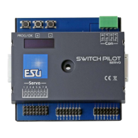
Highlights eight RC servo outputs and precise control capabilities for various movements.
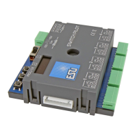
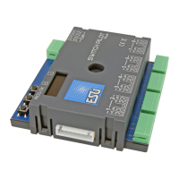
Details technical specifications including input voltage, outputs, power, modes, configuration, and dimensions.
Lists the items included with the SwitchPilot 3 Servo, such as the main unit and terminal blocks.
Explains the two servo operating modes: Digital mode for fixed positions and Proportional mode for variable positions.
Discusses compatibility with analog, digital, and ESU servo drives, noting specific characteristics and settings.
Identifies and explains the function of each terminal and pin header on the SwitchPilot 3 Servo unit.
Details powering the device directly from the command station or booster, ideal for programming track use.
Recommends an external stabilized DC power supply for larger layouts, specifying voltage and current requirements.
Guides on connecting RC servos to the 8 outputs, specifying voltage supply and pulse wire identification.
Explains connecting the SwitchPilot Extension module for relay outputs and powering DC turnout motors.
Details how to use the SwitchPilot Extension module for easily polarizing turnout frogs.
Explains how accessory addresses map to turnout numbers based on digital system (Motorola/DCC) and group assignments.
Explains the 'panel' structure of the OLED display for parameter configuration using the 3-button interface.
Instructs to set the decoder mode to 'ROCO' for compatibility with ROCO® command station address calculations.
Guides on setting servo end positions (Pos A/B), movement speeds, and selecting the operating mode (Digital/Proportional).
Covers adjusting servo pulse parameters to prevent buzzing/jerking and managing servo power supply.
Enables assigning multiple servos to a single function button (turnout number) for combined operation.
Details how to view decoder status, including software versions, voltage, and output states (position, command).
Notes that no special connections are needed for POM configuration; existing wiring is sufficient.
Details the process of reading and writing CVs using Programming on the Main (POM) via a command station.
Describes connecting the device to the digital system's programming track for CV reading and writing.
Discusses reading/writing CVs via programming track, noting potential issues and alternatives.
Covers the configuration options for RailCom®, including enabling/disabling the feature.
Provides a method to reset the decoder to factory defaults using the programming button and power cycle.
Explains resetting the decoder via DCC systems by writing to CV 8, noting potential command station messages.
Describes how to perform a factory reset directly through the decoder's onboard OLED display interface.
| Brand | Esu |
|---|---|
| Model | SwitchPilot 3 |
| Category | Media Converter |
| Language | English |