10
Connection to the digital system
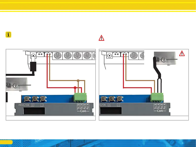
5.2. Power supply by the digital system
For smaller layouts with only a few electric loads turned on at the
same time, the SwitchPilot 3 can be supplied directly from the
command station or booster. The terminals Pw A and Pw B are
connected parallel to the terminals Trk A and Trk B.
This wiring scheme must be used if you want to configure the
SwitchPilot 3 Servo on the programming track of your command
station. For more information, see Chapter 9.
5.3. External power supply
For larger layouts with many electric loads, we recommend the
use of an external power supply. DC and AC power supplies are
suitable with the specifications described in chapter 4.2. We re-
commend the use of a stabilized DC power supply with at least
14V DC at least 3A output power (e.g.: ESU part number 50119).
This type of wiring cannot be used for programming on the pro-
gramming track. In this case, a temporary connection must be
established as shown in chapter 5.2.
B 0
Main track exit
min. 18V
B 0
Main track exit
approx.
14V
Stabilized DC
power supply
recommended
Figure 5: Supply from the digital system
Figure 6: Separate (external) power supply