6
4.4. Operating modes
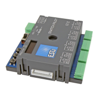
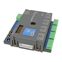
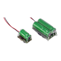
You may connect RC servos directly to any of the 8 outputs of the
SwitchPilot 3 Servo. Contrary to geared motors, servo motors are
intelligent actuators with integral intelligence that can self-reliantly
move to the desired position and remain there. During this process
they apply different power and angular frequency. If any resistance
(force) is applied against the lever, then the servo will be regulated
in order to always reach the pre-determined angle.
The required position is determined via an impulse wire (orange
in case of Graupner® servos, otherwise white). A continuous po-
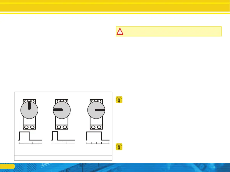
wer supply (4.8V – 6V) completes the interface. Every 20 – 25ms
the servo expects to receive a positive impulse on the pulse wire
with a duration of 1.0ms to 2.0ms. The duration of the impulse is
directly proportional to the desired position. Fig. 1 illustrates the
correlation.
There are servos of many different types and design sizes. They
also differ in their gear reduction ratio and the adjustment travel.
Thus, there are, for instance, servos for adjusting sails that make
several turns.
Operating modes
There are many different types of servos on the market and not all
of them are suitable for use with model trains.
Never try to move the turning lever manually! The gears of the
servo may be damaged!
In general, there are two types of operating modes for servos.
They can be individually set for each output.
4.4.1. Digital mode
In digital mode and subject to the settings of the control panel
every servo can move to two end positions “A” and “B”. With the
SwitchPilot 3 Servo you can adjust both end positions as well as
the speed at which the servo moves from “A” to “B”.
In digital mode every servo will always stop at one of the two end
positions “A” or “B”, never in between.
As an option one can determine if the servo pulse should be con-
tinuously switched on or should only be active during movement.
This is helpful when operating analogue servos. Furthermore, one
can determine if the supply voltage should be turned off once the
servo has reached the desired end position.
The digital mode is perfectly suitable for controlling turnouts or
signals that should always remain in a fixed position.
4.4.2. Proportional mode
For the first time the proportional mode is instituted with the
SwichPilot 3 Servo and replaces the previously known positions
“C” and “D” of servos.
In proportional mode the servo can move and stop at any position
between the end position “A” and “B”. The servo moves as long
as the control panel transmits a command. Once you release the
button, the servo stops. Thus, you can stop the servo at any desi-
red position. The speed of movement is adjustable.
The proportional mode is ideally suited for applications like water
standpipes for steam locomotives or gates of engine sheds. In fact,
for any other application that requires in between positions.
Figure 1: Impulse control of RC servos
2.50ms
2.00ms
1.50ms
1.00ms
0.00ms
2.50ms
2.00ms
1.50ms
1.00ms
0.00ms
2.50ms
2.00ms
1.50ms
1.00ms
0.00ms
1.50 ms: neutral 1.00 ms: 0° (left) 2.00 ms: 180° (right)