12
Wiring the outputs
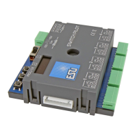
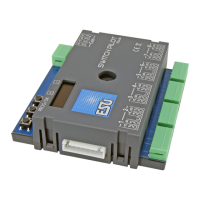
5.5. Connecting the SwitchPilot Extension
Up to two SwitchPilot Extension Modules can be docked to the
side of the SwitchPilot 3 Servo. To do this, press the modules with
the 8-pin plugs against each other until the latches on the plugs
engage. The internal logic and the relay coils of the SwitchPilot
extension module are also supplied by the SwitchPilot 3 servo.
The SwitchPilot Extension module on the left is responsible for
outputs 1 to 4, the SwitchPilot Extension module on the right is
responsible for outputs 5 to 8.
5.5.1. Relay outputs
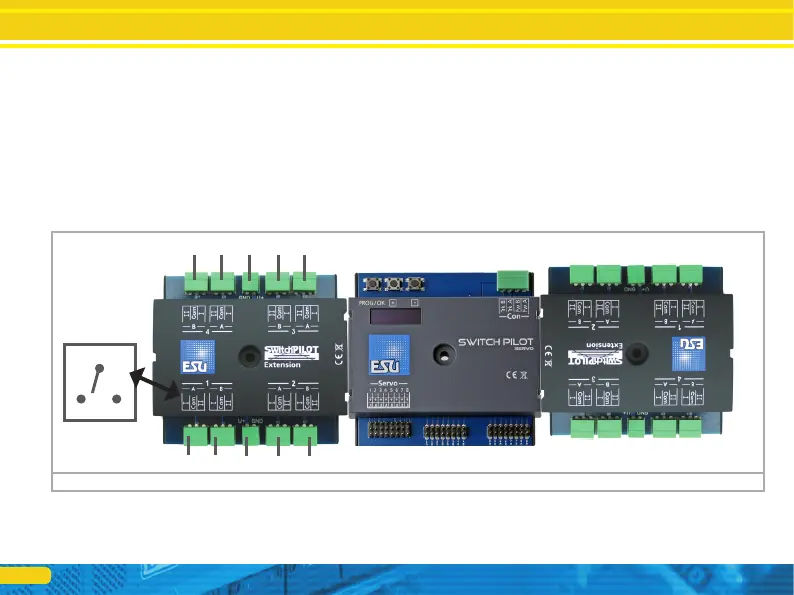
Fig. 8 shows the connections:
a) The outputs 1 to 4 are connected to relay outputs A and B,
which are activated jointly (2x change-over contacts, bistable).
Each relay output corresponds to the corresponding transistor
output of the SwitchPilot 3. If the output Out A of the Switch-
Pilot 3 is active, the terminals I and COM of the relay output
are also active. If the output Out B on the SwitchPilot 3 is
active, terminals II and COM are also active.
b) Terminals for ground and „U+” (rectified track voltage, sup-
plied by SwitchPilot 3) for powering DC turnout motors.
Figure 8: SwitchPilot Servo with two mounted SwitchPilot Extension modules
a) a)
b) a) a)
a) a)
b) a)
a)
I
II
Com
For outputs 5 bis 8For outputs 1 bis 4