2
Contents
1. Declaration of conformity1. Declaration of conformity
1. Declaration of conformity1. Declaration of conformity
1. Declaration of conformity
....................................................................................
....................................................................................
..........................................
33
33
3
2. WEEE declaration2. WEEE declaration
2. WEEE declaration2. WEEE declaration
2. WEEE declaration
..............................................................................................................
..............................................................................................................
.......................................................
33
33
3
3. Important notes – Please r3. Important notes – Please r
3. Important notes – Please r3. Important notes – Please r
3. Important notes – Please r
ead this chapter firstead this chapter first
ead this chapter firstead this chapter first
ead this chapter first
....................
....................
..........
44
44
4
4. How this manual will help you4. How this manual will help you
4. How this manual will help you4. How this manual will help you
4. How this manual will help you
......................................................................
......................................................................
...................................
44
44
4
5. Intr5. Intr
5. Intr5. Intr
5. Intr
oduction – The SwitchPilot familyoduction – The SwitchPilot family
oduction – The SwitchPilot familyoduction – The SwitchPilot family
oduction – The SwitchPilot family
..................................................
..................................................
.........................
55
55
5
5.1. Members of the SwitchPilot family ............................... 5
5.1.1. SwitchPilot Decoder at a glance ................................ 5
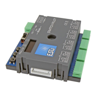
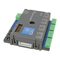
5.1.2. SwitchPilot ................................................................ 5
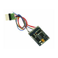
5.1.3. SwitchPilot Servo ....................................................... 6
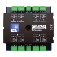
5.1.4. SwitchPilot Extension ................................................ 6
5.2. Features ....................................................................... 6
5.2.1. Operational modes ................................................... 6
5.2.1.1. k83 mode .............................................................. 6
5.2.1.2. k84 mode .............................................................. 7
5.2.1.3. User mode ............................................................. 7
5.2.2. Transistor outputs ...................................................... 7
5.2.3. Servo outputs ............................................................ 7
5.2.4. Relay outputs ............................................................ 8
5.2.5. Feedback signal input ............................................... 8
5.2.6. Switching input ......................................................... 8
6. Connecting to the digital system6. Connecting to the digital system
6. Connecting to the digital system6. Connecting to the digital system
6. Connecting to the digital system
................................................................
................................................................
................................
88
88
8
6.1. Terminals of the SwitchPilot ......................................... 8
6.2. Terminals of the SwitchPilot Extension ......................... 9
6.3. Terminals of the SwitchPilot Servo ............................. 10
6.4. Power supply from the digital system ......................... 11
6.5 Separate power supply ............................................... 11
6.6. Wiring of the SwitchPilot Extension ........................... 11
6.7. Wiring of the transistor outputs ................................. 12
6.7.1. Connecting double-coil solenoids ........................... 12
6.7.2. Wiring of daylight signals and light bulbs or LEDs ..... 13
6.7.3. Wiring of a motor drive .......................................... 13
6.8. Wiring of a servo ....................................................... 14
6.9. Wiring of feedback contacts ...................................... 14
6.10. Polarizing electric frogs ............................................ 15
7. Decoder settings (pr7. Decoder settings (pr
7. Decoder settings (pr7. Decoder settings (pr
7. Decoder settings (pr
ogramming)ogramming)
ogramming)ogramming)
ogramming)
............................................................
............................................................
..............................
1515
1515
15
7.1. Changeable decoder features .................................... 15
7.1.1. Configuration Variables (CVs) ................................. 15
7.1.1.1. Standardization regarding NMRA......................... 15
7.1.1.2. Bits and bytes ....................................................... 16
7.2. Programming with DCC systems ................................ 16
7.2.1. Programming on the main track ............................. 16
7.2.2. Programming on the programming track ................ 16
7.2.2.1. Connecting to the programming track ................. 17
7.3. Programming with Märklin® central stations ............. 17
7.4. Programming with the ESU LokProgramer ................. 18
8. Addr8. Addr
8. Addr8. Addr
8. Addr
ess settings
ess settings
ess settingsess settings
ess settings
..............................................................................................................
..............................................................................................................
.......................................................
1818
1818
18
8.1. Turnout numbers ........................................................ 18
8.2. Decoder addresses ..................................................... 18
8.2.1. Schedule of turnout numbers and addresses .......... 18
8.3. Factory settings .......................................................... 20
8.4.
Programming addresses with the programming button ....
20
8.4.1. First address for outputs 1 – 4 ................................. 20
8.4.2. Second address for outputs 5 – 6 ............................ 20
9. Featur9. Featur
9. Featur9. Featur
9. Featur
es of transitor outputses of transitor outputs
es of transitor outputses of transitor outputs
es of transitor outputs
........................................................................
........................................................................
....................................
2121
2121
21
9.1. Configuration for impulse output (k83) ..................... 21
9.2. Configuration for preset pulse time ........................... 21
9.3. Configuration for PECO turnout motors ..................... 21
9.4. Configuration for alternate blinking mode ................ 21
9.5. Configuration for variable (k84) ................................. 21
9.6. Configuration for „zoom“effect for impulse output .. 21
10. Featur10. Featur
10. Featur10. Featur
10. Featur
es of servo outputses of servo outputs
es of servo outputses of servo outputs
es of servo outputs
..............................................................................
..............................................................................
.......................................
2121
2121
21
10.1. Configuration of servo end position „A“ ................. 21
10.2. Configuration of servo end position „B“ ................. 21