21
9. Parameters of the transistor outputs
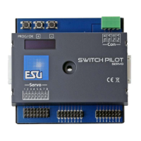
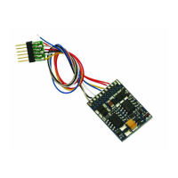
SwitchPilot
In order to set the parameters of the transistor outputs 1 to 4
each is assigned to a configuration-CV: CV 3 is responsible for
output 1, CV 4 for output 2, CV 5 for output 3 and CV 6 for
output 4.
9.1. Configuration of an output with variable duration (k83)
Write the value 0 in the appropriate CV. The output will then
behave as follows: the output is active as long as the
corresponding button on the control panel is pressed. Once you
release the button the output will switch off immediately. This is
useful for un-couplers amongst others.
9.2. Output configuration to pulsed output with fixed pulse duration
Write a value between 2 and 31 into the configuration-CV if you
wish the output to generate a pulse of a pre-determined duration
regardless of how long you actually press the button. This value
describes the duration of the on-period as a multiple of 65 msec.
The higher this value, the longer is the on-period.
Example:
You want to have an output lasting about one second. Write the
value 15 into the CV (16 * 65 msec = 975 msec)
9.3. Configuration of an output for PECO solenoid drives
If you wire a PECO solenoid drive to an output write the value 1
into the corresponding configuation-CV. This adjusts the overload
(over current) protection to the higher values for PECO solenoid
drives.
If you would like to use PECO turnout motors you have to use an
external transformer to supply the SwitchPilot with enough
current. See section 6.5
9.4. Configuration of an output as alternating blinker
If you wish to set the two transistor outputs into the alternating
blinking mode (for instance for levels crossings) then write a value
between 32 and 64 into the CV. This value describes the duration
of the on-period (blinking) as a multiple of 130 msec.
9.5. Configuration of an output for continuous operation (k84)
If you wish to alternately activate one of the transistor outputs
until the other one is switched on then write the value 64 into
the configuration-CV.
9.6. Configuring the „zoom“-effect
The lights of prototype daylighting signals do not come on within
a split second but rather take a few moments until they reach
full output respectively until they extinguish fully. This effect can
be simulated by programming the “zoom”- function to each
output in CV 34. Please refer to the table in chapter 17.
10. Features of servo outputs
Two end positions „A“ and „B“ as well as a turning speed can
be assigned to each servo output.
If your digital command station supports programming on the
Main (POM) you may fine tune these CVs in normal operating
mode. Change the settings of the relevant CVs step by step until
the servo reaches the desired end position.
In case you are using a SwitchPilot Servo we recommend using
the input unit to set the end positions. See Chapter 10.4.
10.1. Configuration of servo end position „A“
The end position „A“ of the servo can be set in CV 38, 41, 44
and 47. The precise value depends on the type of servo and the
installation. This can only be established by experimenting.
10.2. Configuration of servo end position „B“
The end position „B“ of the servo can be set in CV 39,42.45 and
48. The precise value depends on the type of servo and the
installation. This can only be established by experimenting.