12
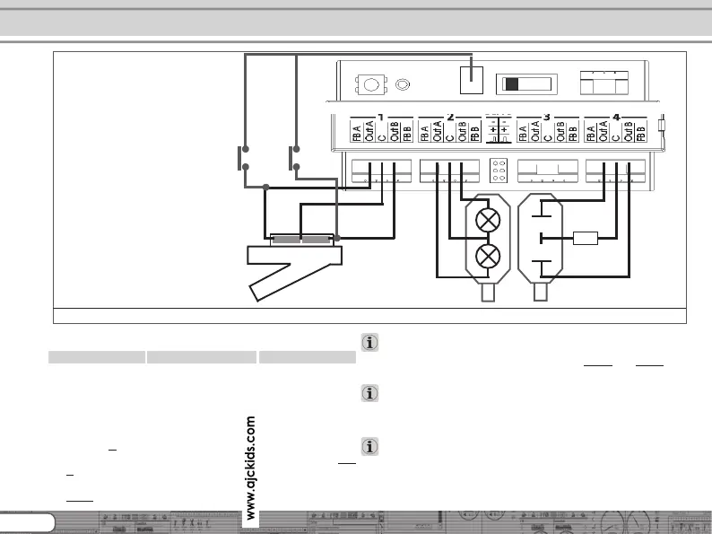
6.7. Wiring of transistor outputs
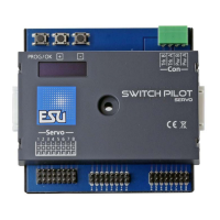
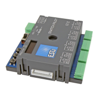
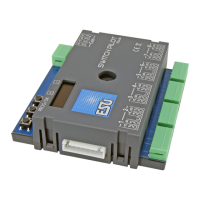
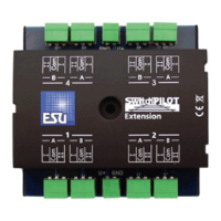
SwitchPilot
6.7.1. Connecting double-coil solenoids
You may use all commercially available double-coil solenoid drives
by all major manufacturers with SwitchPilot. Figure 4 shows how
to wire output 1:
a) The common wire of the solenoid is wired to screw
terminal
C.
b) The wire leading to the first coil is connected to terminal
Out
A.
c) The wire leading to the second coil is connected to terminal
Out B.
Should the aspect shown on your control panel not be as desired
(in other words: if straight and diverging route are exchanged)
simply swap the wires between terminals
Out A and Out B.
SwitchPilot can also handle PECO® turnouts. However, their
current consumption is so high that you must adjust the overload
setting of the SwitchPilot. Please refer to chapter 9.3. for details.
As shown in Figure 5 the double-coil turnouts can be switched
with two optional push buttons without a digital command. The
needed ground solder pad is not available on all SwitchPilot
surfaces.
How to wire transistor outputs
Figure 5: Connection to transistor outputs 1 - 4
R
a)
b)
c)
Activation through
button is possible
(Ground solder pad is
not available on all
models).