– The manufacturer is not responsible for damage caused by improper use of the appliance
and the accessories and its warranty for the appliance does not apply in situations when
the safety warnings above are not complied with. Failure to replace or maintain all filters
regularly according to the instructions in Chapter IV., V. and also using non-original
filters, the properties of which resulted in failure or damage of the vacuum cleaner, is also
understood to be improper use of the appliance.
For trouble-free operation of the vacuum cleaner, please use the
tested dust filters and micro-filters recommended by the producer.
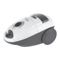
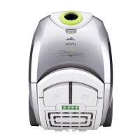
II. EQUIPMENT AND ACCESSORIES (fig. 1)
A – vacuum cleaner
A1 – suction vent A9 – handle
A2 – lid A10 – power cord
A3 – lid lock A11 – parking holes
A4 – START/STOP button A12 – exhaust grid
A5 – power cord winding button A13 – exhaust HEPA micro-filter
A6 – electric motor regulation A14 – filter holder
A7 – full filter signaling A15 – dust filter (ETA ORIGINAL MINI)
A8 – suction micro-filter
B – accessories
B1 – floor nozzle B5 – upholstery nozzle
B2 – suction hose B6 – brush
B3 – suction tube B7 – parquet nozzle
B4 – crevice nozzle
Caution: attachments it is possible to buy these accesories with marks.
III. VACUUM CLEANER PREPARATION
Hose
– Connect hose B2 to the vacuum cleaner by inserting the end piece to suction vent A1
to the maximum position and turn to the right (Fig. 4). You will hear a clicking sound.
– To disassemble proceed in the reverse sequence.
Telescopic tube
– You can connect tube B3 with hose handle B2 by slight pushing the handle to the tube
(Fig. 3).
– You can disconnect the tube by pulling the handle slightly out of the tube.
– The telescopic tube allows setting suitable length to fit your figure. Press the lock pin
in the direction of the arrow and pull out or push in the required length of the tube (Fig. 3).
When you release the lock projection, the tube length is fixed. When pulling out, keep
the tube in safe distance from your face as the tube is very long.
Floor nozzle / narrow floor nozzle
– Connect and disconnect the accessories (B1, B7) in the same way as the tube (Fig. 2).
22
GB
/ 48