22 DSC2P Hardware Manual
ETEL Doc. - Hardware Manual # DSC2P / Ver H / 6/1/11
3. Electrical interface
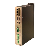
This chapter describes the pin assignment for every connector. More detailed explanations for proper
connections are given in each case.
There are six groups of connectors, according to their function:
Encoders connectors (see §3.1
).
Inputs / outputs connectors (see §3.2
).
Communication connectors (see §3.3
).
Motor connector (see §3.4
).
Power connector (see §3.5
).
Optional boards connector (see §3.6
).
Warning: High voltage may be present on the power and motor connectors.
Before connecting or disconnecting a cable on one of these connectors or touching
the controller, turn off all the power supplies and wait 10 minutes to allow the
internal DC bus capacitors to discharge.
Caution: All the inputs/outputs cables must be insulated (no contact) from the power and
the mains.
The inputs and outputs must be connected to an Extra Low Voltage circuit only
(SELV).
Most inputs and outputs are not galvanically insulated from the GND.
The motor connector must always be correctly screwed onto the DSC2P.
Caution: All the connectors must be handled in an ESD protected environment, only.
Remark: In the next paragraphs, connectors with male pins are indicated with the • symbol (full), and
female pins are represented with the ο symbol (empty).
Artisan Technology Group - Quality Instrumentation ... Guaranteed | (888) 88-SOURCE | www.artisantg.com

 Loading...