30 DSC2P Hardware Manual
ETEL Doc. - Hardware Manual # DSC2P / Ver H / 6/1/11
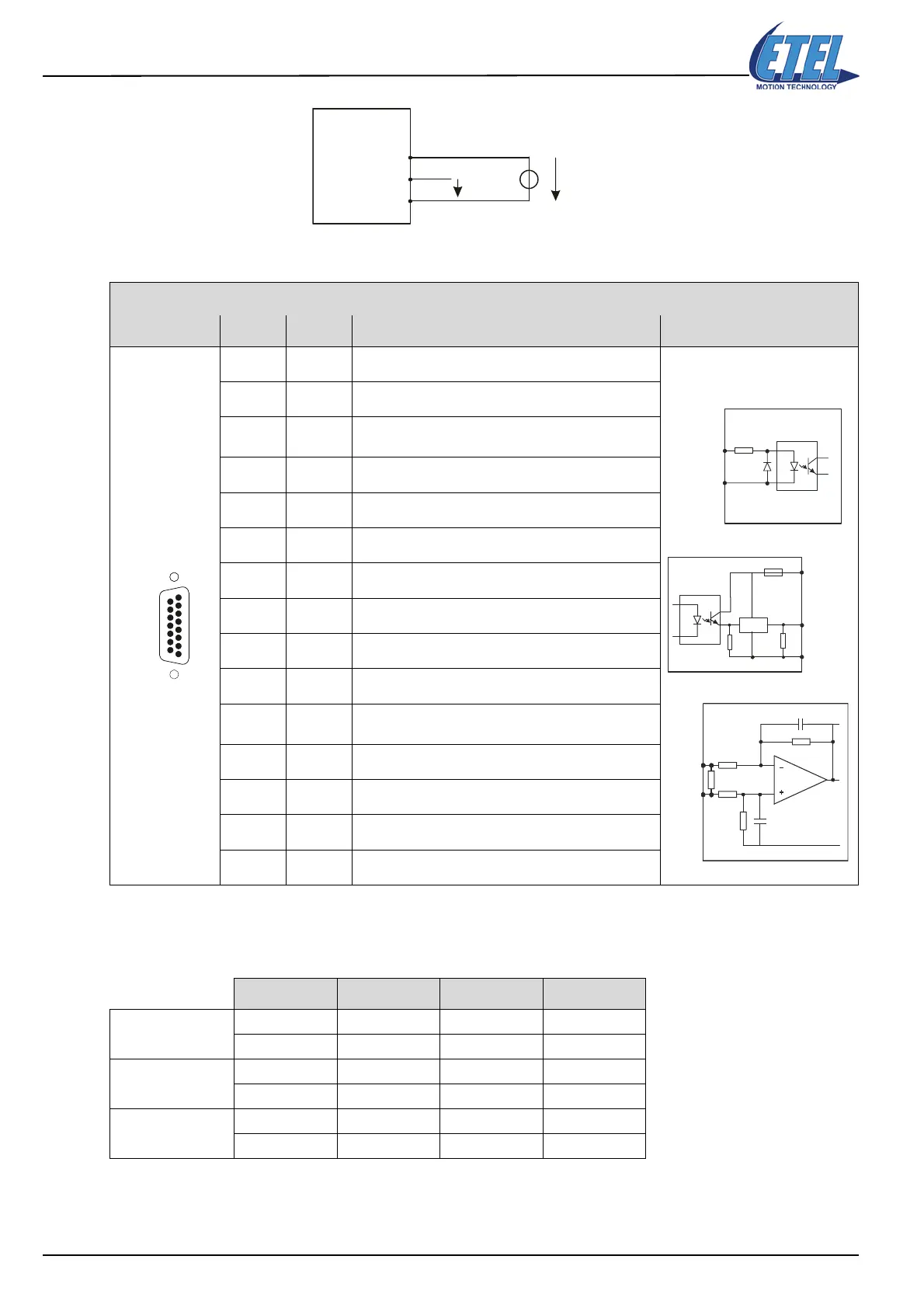
Remark: This diagram shows the use of DOUT1, but it is the same with DOUT2, DOUT3 and DOUT4.
Remark: The converter used for the analog input is a 12 bits converter.
The commutation times of the above-mentioned inputs and outputs are as follows:
Remark: The above-mentioned times takes only the hardware into account. To have the entire time, a delay
(max. 1 STI) must be added to these times, to take the treatment of the command by the software
into account.
D-SUB, 15 pins, male
CUSTOMER I / O Pin # Signal Function Interface
1 GND Auxiliary supply output (0V)
2 AIN1 + Analog input 1 +
3GNDext
External supply input (0V) for the digital inputs and
outputs
4 DOUT1 Digital output 1 +
5 DOUT3 Digital output 3 +
6 DIN1 + Digital input 1 +
7 DIN3 + Digital input 3 + (high speed 100ns)
8 DIN9 + Digital input 9 + (high speed 100ns)
9 AIN1 - Analog input 1 -
10 DOUT4 Digital output 4 +
11 +Vext
External supply input for digital outputs (protected by
fuse F2 of 500mA - limits user's input current)
12 DOUT2 Digital output 2 +
13 DIN2 + Digital input 2 +
14 DIN4 + Digital input 4 + (high speed 100ns)
15 DIN10 + Digital input 10 + (high speed 100ns)
Status Typical Maximum Unit
DOUTs
0 => 1 50 55 μs
1 => 0 300 330 μs
DINs 3, 4, 9 and 10
(high speed)
0 => 1 100 110 ns
1 => 0 600 660 ns
DINs 1 and 2
0 => 1 4 5 μs
1 => 0 40 50 μs
DSC2P
+Vext
(+12VDC → +28VDC)
+Vext
DOUT1
GNDext
11
4
3
DOUT1
DSC2P
DIN1+
to
DIN4+
DIN9+
DIN10+
GNDext
F2
DSC2P
GNDext
DOUT1
to
DOUT4
+Vext
BSP450
33 kΩ
DSC2P
AIN1+
R
R
C
AIN1-
+/- 10V
C
R
Artisan Technology Group - Quality Instrumentation ... Guaranteed | (888) 88-SOURCE | www.artisantg.com

 Loading...