24-Port Web-Smart Ethernet Switch
User’s Manual
7
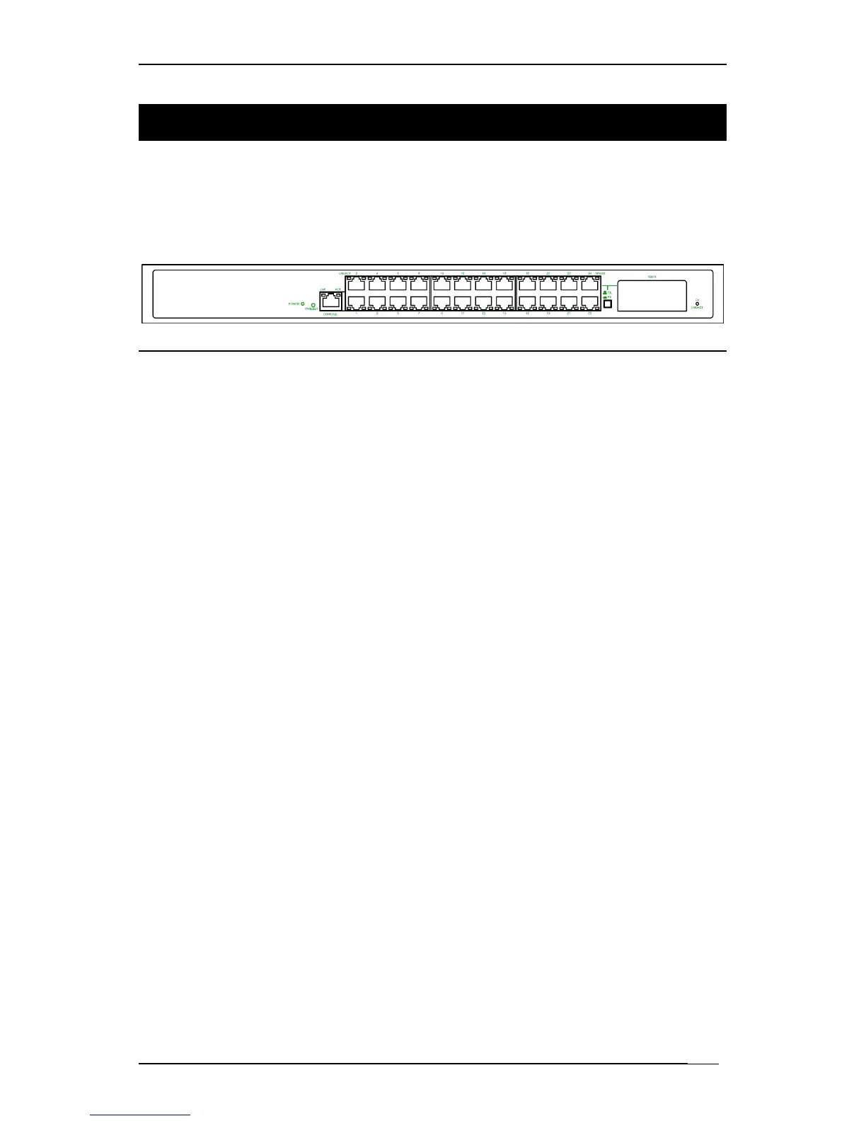
Front Panel Display
The LED indicators on the front panel provide you with instant
feedback on each port status, and help you monitor and
troubleshoot the switch.
Figure 2: Front Panel LEDs
Power
This LED comes on when the switch is properly connected to power and
turned on.
Push Button
The push button is located at the right side of port 24 on the 24-Port Switch.
Depress this button to use twisted pair port 24, and press this button to use
the 100Base-FX module.
IP RESET Push Button
Press the Front panel IP RESET push button around five seconds to reset
the Ethernet Switch back with the default IP Address.
Port Status
The RJ-45 ports are numbered from 1 to 24 on the 24-Port Switch.
The LEDs are located on the ports of the switch, displaying status for each
respective port. Please refer to the table below for more information.
Consult the following table for details.
L Before you use this table for troubleshooting, make sure the switch is
properly connected to power and turned on.