Operating Instructions
Non-Contact Safety Switch CES-AP-C01-…
12
(Translation of the original operating instructions) 2112663-08-02/20
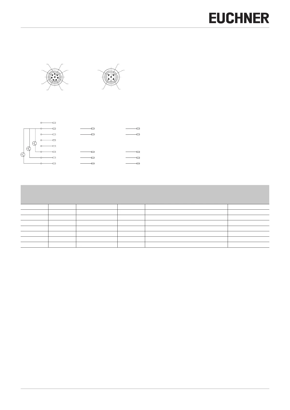
9.5. Connector assignment of safety switch CES-AP-C01
View of connection side on the safety switch
Plug connector
8
2
7
6
1
3
4
5
UB
0V
n.c.
n.c.
OA
OB
DIA
RST
1
3
2
4
5
UB
0V
OA
OB
DIA
1
3
2
4
5
UB
0V
OA
OB
n.c.
8
2
7
6
1
3
4
5
UB
0V
n.c.
n.c.
OA
OB
DIA
RST
1
3
2
4
5
UB
0V
OA
OB
DIA
1
3
2
4
5
UB
0V
OA
OB
n.c.
8-pin 5-pin
8
2
7
6
1
3
4
5
UB
0V
n.c.
n.c.
OA
OB
DIA
RST
1
3
2
4
5
UB
0V
OA
OB
DIA
1
3
2
4
5
UB
0V
OA
OB
n.c.
8-pin 5-pin 5-pin;
pin 5 not used
Figure 1: Connector assignment of safety switch CES-AP-C01
Pin
Plug connector
Designation Description Conductor coloring
8-pin 5-pin
5-pin,
pin 5 not used
1 - - n.c. Not used WH
2 1 1 UB Power supply, DC 24 V BN
3 2 2 OA Safety output, channel 1 GN
4 4 4 OB Safety output, channel 2 YE
5 5 - DIA Monitoring output GY
6 - - n.c. Not used PK
7 3 3 0V Ground, DC 0 V BU
8 - - RST Reset input for hardware reset RD

 Loading...


