Operating Instructions
Safety Hinge ESH Readjustable
4
Subject to technical modications; no responsibility is accepted for the accuracy of this information. © EUCHNER GmbH + Co. KG 109804-04-03/16 (translation of the original operating instructions)
Inspection and service
WARNING
Danger of severe injuries due to the loss of the
safety function.
f If damage or wear is found, the complete switch
must be replaced. Replacement of individual
parts or assemblies is not permitted.
f Check the device for proper function at regular
intervals and after every fault. For informa-
tion about possible time intervals, refer to
ENISO14119:2013, section 8.2.
Inspection of the following is necessary to ensure
trouble-free long-term operation:
f correct switching function
f secure mounting of all components
f damage, heavy contamination, dirt and wear
f sealing of cable entry
f loose cable connections or plug connectors.
Information: The year of manufacture can be seen
in the bottom, right corner of the type label.
Exclusion of liability and warranty
In case of failure to comply with the conditions for
correct use stated above, or if the safety instruc-
tions are not followed, or if any servicing is not
performed as required, liability will be excluded and
the warranty void.
Notes about
The following information applies to devices
with plug connector:
For use and applications as per the requirements of
, a class 2 power supply according to UL1310
must be used. Connection cables for safety switches
installed at the place of use must be separated
from all moving and permanently installed cables
and un-insulated active elements of other parts
of the system which operate at a voltage of over
150V. A constant clearance of 50.8 mm must be
maintained. This does not apply if the moving cables
are equipped with suitable insulation materials which
possess an identical or higher dielectric strength
compared to the other relevant parts of the system.
EC declaration of conformity
The manufacturer named below herewith declares
that the product fullls the provisions of the direc-
tive(s) listed below and that the related standards
have been applied.
EUCHNER GmbH + Co. KG
Kohlhammerstr. 16
D-70771 Leinfelden-Echterdingen
Directives applied:
f Machinery directive 2006/42/EC
Standards applied:
f EN60947-5-1:2004 + Cor.:2005 + A1:2009
f EN1088:1995+A2:2008
f EN14119:2013
The original EC declaration of conformity can also
be found at: www.euchner.de
Service
If service support is required, please contact:
EUCHNER GmbH + Co. KG
Kohlhammerstraße 16
D-70771 Leinfelden-Echterdingen
Service telephone:
+49 711 7597-500
Fax:
+49 711 753316
E-mail:
support@euchner.de
Internet:
www.euchner.de
Technical data
Parameter Value
Housing material Die-cast zinc, nickel-plated
Degree of protection acc. to
IEC 60529
IP 67
Mech. operating cycles 1x10
6
Ambient temperature -25 °C ... +70 °C
Degree of contamination
(external, according to EN
60947)
3 (industrial)
Installation position Any
Weight 0.77 kg
Max. load as per mechanical
life test acc. to EN 1935
Door hinge class 12
(100 kg door weight)
Pivoting angle -10° … 180°
Operating point 4° from xing point
Positively driven Approx. 10° from xing point
Actuation frequency Max. 1200 operating cycles / h
Switching principle Snap-action switching contact
Contact material Silver alloy
Connection Plug connector M12 / 5-pin
Rated impulse withstand
voltage
2.5 kV
Rated insulation voltage 60 V
Conditional short-circuit
current
100 A
Utilization category according to EN 60947-5-1
AC-15
DC-13
1.5 A 30 V
2.0 A 24 V
Switching current, min., at
24 V
1 mA
Short circuit protection
(control circuit fuse) acc. to
IEC 60269-1
2 A gG
Conventional thermal cur-
rent I
th
3 A
Reliability values according to EN ISO 13849-1
B10d 2 x 10
6
Version
ESH-PRO-20A-1205
Version
ESH-PRO-11A-1205
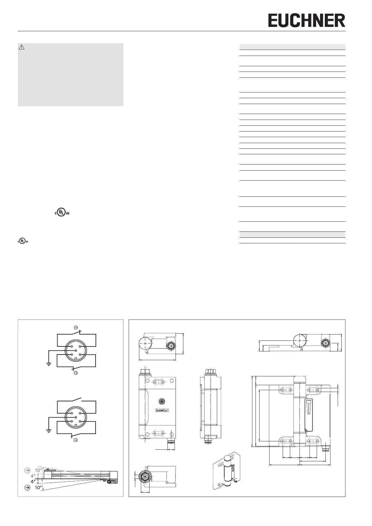
Figure 1: Pin assignment plug M12/5-pin, switching
elements and travel diagram
Figure 2: Dimension drawing safety hinge ESH
M
12
x1
SW
14
SW
6
34
60
6,5
(4x)
16 16 1212
50
42,5
50
27,4
17
9,4
12,9
84
115
100 14,50
Dimensions as supplied Dimensions operating point xed
 Loading...