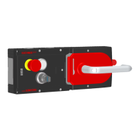
Operating Instructions Safety Systems
MGB-L1…-AR.-… / MGB-L2…-AR.-… and MGB-L1…-AP.-… / MGB-L2…-AP.-…
28
(Translation of the original operating instructions) 2119167-06-10/20
12.7. Notes on operation with control systems
Please observe the following requirements for connection to safe control systems:
General notes
Ì Use a common power supply for the control system and the connected safety switches.
Ì A pulsed power supply must not be used for UB/UA. Tap the supply voltage directly from the power supply unit. If the
power supply is connected to a terminal of a safe control system, this output must provide sufcient electrical current.
Ì The safety outputs (FO1A and FO1B) can be connected to the safe inputs of a control system. Prerequisite: the input
must be suitable for pulsed safety signals (OSSD signals, e.g. from light grids). The control system must tolerate test
pulses on the input signals. This normally can be set up by parameter assignment in the control system. Observe the
notes of the control system manufacturer. For the pulse duration of your safety switch, please refer to chapter 14. Tech-
nical data on page 36.
Ì The inputs on a connected evaluation unit must be positive switching, as the two outputs on the safety switch deliver a
level of +24V in the switched-on state.
AR
Ì Always connect inputs FI1A and FI1B directly to a power supply unit or to outputs FO1A and FO1B of another
EUCHNER AR device (series connection). Pulsed signals must not be present at inputs FI1A and FI1B.
The test pulses are also present when the safety outputs are switched off (only on FO1A). Depending on the
inertia of the downstream device (control system, relay, etc.), this can lead to short switching processes.
Guard locking control
Ì Test pulses up to max. 5ms in duration at intervals of min. 100ms are tolerated on IMP1, IMP2 and IMM.
NOTICE
Due to the fact that short circuit monitoring of the safety outputs FO1A/FO1B is performed by the
device itself, the Performance Level in accordance with EN13849 is not reduced if the control system
pulsing is switched off.
Tip!
A detailed example of connecting and setting the parameters of the control system is available for
many devices at www.euchner.com, in the area Service/Downloads/Applications. The features of the
respective device are dealt with there in greater detail.

 Loading...