Operating Instructions Safety Systems
MGB-L1…-AR.-… / MGB-L2…-AR.-… and MGB-L1…-AP.-… / MGB-L2…-AP.-…
30
(Translation of the original operating instructions) 2119167-06-10/20
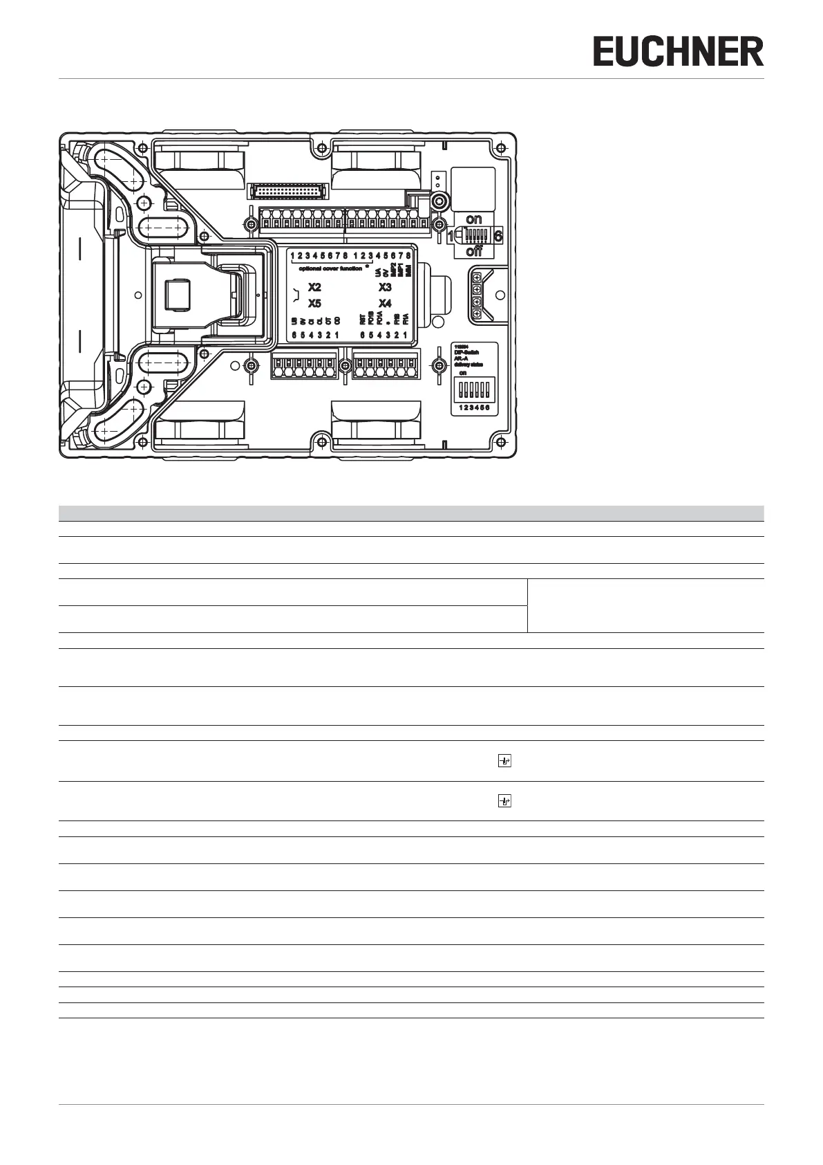
12.9. Terminal assignment and contact description
X3
X4X5
X2
LEDs
Power
DIA 1
DIA 2 RD
State YE
Figure 17: Connections and LEDs
Terminal Designation Description
X3.1 to X3.3 - See the enclosed data sheet
X3.4 UA Power supply for the guard locking solenoid, monitoring outputs and cover assembly, DC24V, must be present continuously so that
the guard locking solenoid functions.
X3.5 0V Ground, DC0V (connected internally to X5.5).
X3.6 IMP2 Control voltage for switching the guard locking on and off, DC24V
(see chapter 12.8. Connection of guard locking control on page 29).
IMP1/IMP2 are usually bridged (jumper) as the default
setting on delivery
X3.7 IMP1 Control voltage for switching the guard locking on and off, DC24V
(see chapter 12.8. Connection of guard locking control on page 29).
X3.8 IMM Control voltage for switching the guard locking on and off, 0V (see chapter 12.8. Connection of guard locking control on page 29).
X4.1 FI1A With AR conguration: enable input for channel A, connect to DC24V in separate operation. In case of switch chains, connect
output signal FO1A from previous device.
With AP conguration: input is not evaluated.
X4.2 FI1B With AR conguration: enable input for channel B, connect to DC24V in separate operation. In case of switch chains, connect
output signal FO1B from previous device.
With AP conguration: input is not evaluated.
X4.3 - See the enclosed data sheet
X4.4 FO1A Safety output channel A (function dependent on DIP switch setting)
Guard lock monitoring active: ON when door is closed and locked .
Guard lock monitoring inactive: ON when door is closed and bolt tongue is inserted.
X4.5 FO1B Safety output channel B (function dependent on DIP switch setting)
Guard lock monitoring active: ON when door is closed and locked .
Guard lock monitoring inactive: ON when door is closed and bolt tongue is inserted.
X4.6 RST Reset input, device is reset if DC24V is applied to RST for at least 3 s.
X5.1 OD Door monitoring output,
ON when the door is closed.
X5.2 OT Bolt tongue monitoring output,
ON when the door is closed and the bolt tongue is inserted into the locking module.
X5.3 OL Guard lock monitoring output,
ON when the door is closed and locked.
X5.4 OI Diagnostics monitoring output,
ON when the device is in the fault state.
X5.5 0V Ground, DC0V
(connected internally to X3.5).
X5.6 UB Power supply, DC24V
X2.1 to X2.8 - See the enclosed data sheet
X1 - Reserved for connection of the cover circuit board (only for populated covers)
Table 2: Terminal assignment and contact description

 Loading...