Euphonix FC726 Format Converter Users Manual Pinout and Cable Specifications
36
A.2.3 ProDigi
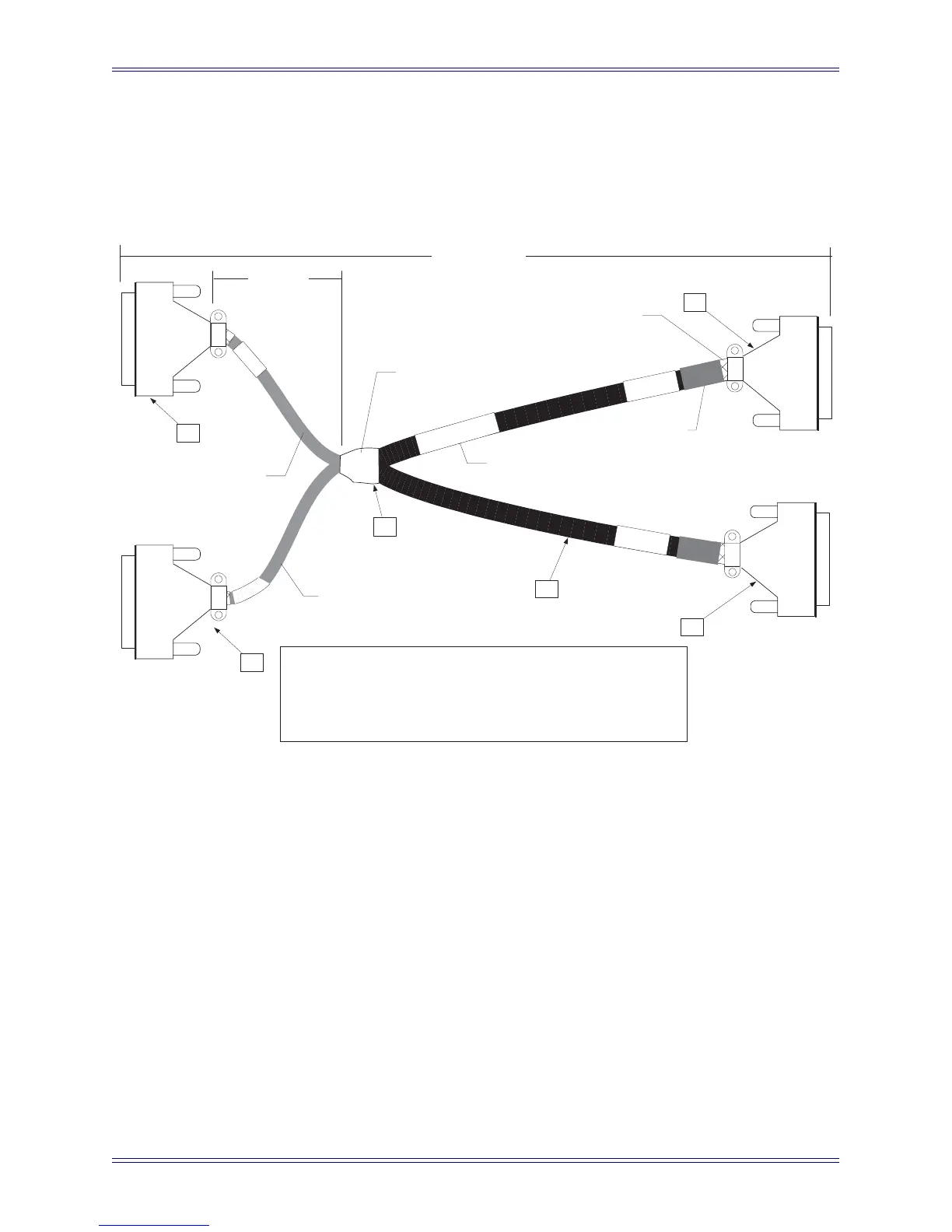
Figure A-4 shows the cable diagram. Table A-5 shows the pinout for the FC726’s
ProDigi connector.
Figure A-4 DB-50 Male/Male-to-DB-50 Male/Female ProDigi cable assembly diagram
PARTS LIST
Item Qty Mfr Mfr P/N Description
1 3 AMP HDP-20 series DB-50 Male
2 1 AMP HDP-20 series DB-50 Female
3
2 inches
3/4" Heatshrink
4
80 inches
Madison
J2
J3
J4
To Pro-Digi
OUT
To Pro-Digi
IN
Label cable with part number and Rev
Pro-Digi
Ch 1-8
10 inches
each pigtail
1
1
4
1
2
4
J1
Approx. 1 meter
(38 to 40 inches)
P/N 030-07660-01
REV B
Pro-Digi
CH 9-16
Portion of braided shield pulled
back over cable insulation to
contact the cable clamp (typical)
Heat shrink to cover braid tails
8 pairs from J3 + 8 pairs from
J4 = 16 pairs total plus several
extra wires in each pigtail to destinations.
Install tubular braid
shield over each
group of wires, then
add heat shrink tubing
Intersection area: Wires from
main trunks cross over and route to
destinations. All braided shields
electrically connected here.
50SDK00130 (or equiv.)
SCSI cable, 25 pairs