51786035X18NXS_V_1_2.DOC
25/55
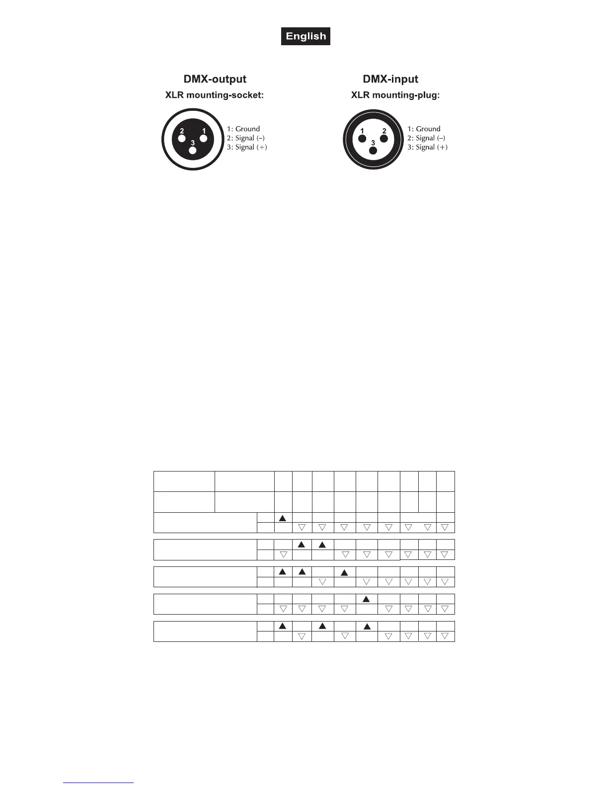
Occupation of the XLR-connection:
If you are using controllers with this occupation, you can connect the DMX-output of the controller directly
with the DMX-input of the first fixture in the DMX-chain. If you wish to connect DMX-controllers with other
XLR-outputs, you need to use adapter-cables.
Building a serial DMX-chain:
Connect the DMX-output of the first fixture in the DMX-chain with the DMX-input of the next fixture. Always
connect one output with the input of the next fixture until all fixtures are connected.
Caution: At the last fixture, the DMX-cable has to be terminated with a terminator. Solder a 120
Ω
resistor
between Signal (–) and Signal (+) into a 3-pin XLR-plug and plug it in the DMX-output of the last fixture.
Addressing
Each projector occupies 5 channels. To ensure that the control signals are properly directed to each
projector, the projector requires adressing. This is to be done for every single projector by changing the DIP
switches as set out in this table.
The starting address is defined as the first channel from which the TS-255 will respond to the controller. If
you set, for example, the address to channel 6, the TS-255 will use the channel 6 to 10 for control.
Please make sure that you don’t have any overlapping channels in order to control each TS-255 correctly
and independently from any other fixture on the DMX data link. If two, three or more TS-255 are addressed
similarly, they will work similarly.
Occupation of the DIP-switches:
Device 1 - channels 1-5
DMX-starting
address
Projector number
& channels
Device 2 - channels 6-10
Device 3 - channels 11-15
Device 4 - channels 16-20
Device 5 - channels 21-25
12
4
8
16
32
64
128
256
DIP-switch no.
12
3
4
5
6
7
8
9
Setting the DMX-
starting address:
On
Off
Off
On
Off
On
Off
On
Off
On
Off
Connection with the mains
Connect the device to the mains with the enclosed power supply cable.
The occupation of the connection-cables is as follows:
 Loading...