EasyManua.ls Logo

Eurotherm 2208L User Manual

Eurotherm 2208L
12 pages
To Next Page IconTo Next Page
Page #1 background imageLoading...
Page #1 background image
-
1
-
HA026202 Issue 2 15/07/99
2216L and 2208L
Temperature Controllers
Installing and Operating Instructions
The 2216L and 2208L are precision PID temperature controllers
ideal for plastic extrusion machines, ovens, chillers and other
heating and cooling processes. The 2216L is in a 48 x 48mm panel
size (1/16 DIN) and the 2208L in a 48 x 96 panel size (1/8 DIN).
Both controllers have up to three outputs for heating, cooling and
alarms. In addition the 2208L has two contact closure inputs to
select second setpoint and standby mode (all outputs off, except
alarms).
The controller will have been built and configured according to
the ordering code given on page 5. Check the ordering code on
the controller side labels to determine the configuration of your
particular controller.
This controller meets the European directives on safety
and EMC.
D
IMENSIONS AND
I
NSTALLATION
Model 2216L
Model 2208L
E
LECTRICAL
C
ONNECTIONS
To install the controller
Please read the safety information on pages 5 & 6 before
proceeding.
Prepare the panel cut-out to the size shown
Insert the controller through the cut-out.
Spring the panel retaining clips into place. Secure the
controller in position by holding it level and pushing both
retaining clips forward.
Unplugging the controller
The controller can be unplugged from its sleeve by easing the
latching ears outwards and pulling it forward out of the sleeve.
When plugging the controller back into its sleeve, ensure that
the latching ears click into place to maintain the IP65 sealing.
Wire Sizes
All electrical connections are made to the
screw terminals at the
rear
of the
controller. These accept wire sizes from
0.5 to 1.5 mm
2
(16 to 22 AWG), and are
protected by a hinged cover to prevent
hands or metal making accidental contact
with live wires. Rear terminal screws
should be tightened to a torque of 0.4 Nm
(3.5 lb in).
.
Setpoint 2
Neutral
Ground
85-264Vac
Heating
Output
Cooling
Output
1B
2A
2B
1A
N
LA
LB
LC
L
AB
AC
VI
V+
V-
AA
Standby
Common
Line
Sensor
input
Alarm
Output
Logic
+
-
or
+
-
Pt100
T/C
Logic
+
-
or
Model 2208L
10mm
(0.4in)
38mm
(1.5in)
(Not to
scale
)
Recommended minimum
spacing of controllers for
both sizes
Neutral
Ground
85-264Vac
Heating
Output
Cooling
Output
1B
2A
2B
3A
3B
1A
N
VI
V+
V-
L
Line
Sensor
input
Alarm
Output
+
-
Pt100
T/C
Logic
+
-
or
Logic
+
-
or
Model 2216L
Output ratings
Relay: 2A, 264Vac resistive
Logic: 18Vdc, 20mA (non-isolated)
Alarm output
The alarm output is non-latching and
de-energised in the alarm state
Grounding
The ground connection is not
required for safety purposes but must
be connected to satisfy EMC
requirements
Panel
cut-out
92 x 45mm
3.62 x 1.77in
96mm
(3.78in)
2208
OP1
OP2
SP2
REM
103mm (4.01in)
48mm (1.89in)
-0
+0.8
-0
+0.6
-0
+0.03
-0
+0.02
DD
DD
DD
DD
Panel retaining clips
RUN
HOLD
2216
MAN
OP1
OP2
SP2
REM
48mm (1.89in)
Panel cut-out
45 x 45mm
-0.0 +0.6
1.77 x 1.77in
-0.00 +0.02
103mm (4.01in)
48mm
(1.89in)
ENG

Other manuals for Eurotherm 2208L

Question and Answer IconNeed help?

Do you have a question about the Eurotherm 2208L and is the answer not in the manual?

Eurotherm 2208L Specifications

General IconGeneral
BrandEurotherm
Model2208L
CategoryTemperature Controller
LanguageEnglish

Summary

Dimensions and Installation

Model 2216L Dimensions

Provides dimensions, panel cut-out, and retaining clip information for the 2216L model.

Model 2208L Dimensions

Provides dimensions, panel cut-out, and spacing recommendations for the 2208L model.

Electrical Connections

Model 2216L Electrical Connections

Details wiring for the 2216L, including output ratings and wire size recommendations.

Model 2208L Electrical Connections

Details wiring for the 2208L, including output ratings and wire size recommendations.

Controller Operation

HOME Display

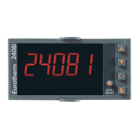
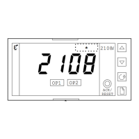
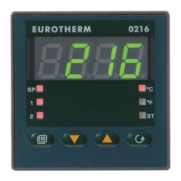
Describes the initial display after a 3-second self-test sequence.

Viewing Display Units

Explains how to view temperature units and momentarily display values.

Using the Scroll Button

Details how to access output power and internal setpoints using the scroll button.

Using the Page Button

Explains how to access parameter lists using the page button.

Alarm Messages

Process Alarms

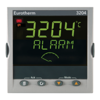
Lists and explains process-related alarm messages like IFSL, FSH, and 3dEu.

Diagnostic Alarms

Lists and explains diagnostic alarm codes such as EE.Er, Err1, and Power Failure.

Parameter Lists Overview

Home List

Parameters for measured temperature and setpoint values.

Alarm List

Parameters for alarm settings including Full Scale Low and High alarms.

Autotune List

Parameter for enabling or disabling the self-tune function.

PID List

Parameters for PID control, including Proportional band and Integral time.

Output List

Parameters related to output power, cycle times, and minimum on times.

On/Off List

Parameters for On/Off control, such as hysteresis settings.

Access List

Parameters for accessing and re-configuring the controller.

Tuning Procedures

Automatic Tuning

Explains automatic PID tuning, including cycle process and cutback calculations.

Manual Tuning

Provides steps for manually tuning PID parameters and setting cutback values.

Manual Reset

Describes how to adjust the manual reset parameter for steady-state error.

Re-Configuration Instructions

Changing Setpoint Limits

Steps to access and modify setpoint limits by changing access levels.

Access List Navigation

Procedure for navigating through access list headers.

Password Entry

How to enter passwords to unlock configuration levels.

Entering Full Access Level

Steps to select and enter the 'FULL' access level for configuration.

Returning to Operator Level

Accessing Operator Level

Steps to return to the 'OPEr' level from higher access levels.

Password for Operator Level

Re-entering the password to regain normal operator access.

Configuration Changes

Changing Temperature Display Units

Procedure to switch between Celsius (°C) and Fahrenheit (°F) display.

Changing Type of Control

Procedure to select between On/Off and PID control modes.

Configuration Level Settings

Temperature Display Units

Setting the temperature units to Celsius or Fahrenheit.

Input Sensor Type

Selecting the type of input sensor, e.g., thermocouple or Pt100.

Type of Control

Selecting the control type: PID control or On/Off control.

Output and Alarm Reconfiguration

Configure Outputs for Heating/Cooling

Reconfiguring outputs 1 and 2 to function as heating or cooling outputs.

Reconfigure Alarm Output

Individually configuring internal alarms for type, latching, and blocking.

Alarm Type Settings

Options for alarm types: disabled, low, high, deviation.

Alarm Latching and Blocking

Settings for alarm latching (non-latching/latching) and blocking.

Return to Operator Level

Ordering Code and Specifications

Ordering Code Structure

Details the structure of the ordering code for controller configuration.

Technical Specifications

Lists environmental ratings, equipment ratings, and electrical specifications.

Safety and EMC Information

Safety Compliance

Information on compliance with Low Voltage and EMC Directives.

General Information

Notes on changeability, accuracy, and liability.

Unpacking and Storage

Instructions for unpacking, handling, and storing the controller.

Service and Repair

Guidance on contacting Eurotherm Controls for service and repair.

Handling Precautions

Warnings regarding charged capacitors and electrostatic discharge.

Cleaning and Symbols

Instructions for cleaning the unit and explanation of safety symbols.

Installation Requirements

Guidelines for personnel, enclosures, live sensors, wiring, and power isolation.

Specific Electrical Considerations

Notes on earth leakage current, voltage rating, and conductive pollution.

Grounding and Over-temperature Protection

Recommendations for sensor shield grounding and over-temperature protection.

Installation Requirements for EMC

EMC Guidance and Wiring

Guidance on EMC installation and routing sensor input wiring.

International Sales and Service

Related product manuals