• mV range +40mV or +80mV
• High level range 0 – 10V
• High Impedance mid level range 0 – 2V. Used for zirconia probe oxygen input.
• A line resistance for voltage inputs may cause measurement errors
Built in Relay (AA)
• Relay shown in de-energised state
• Isolated 240Vac
• Relay rating: Max: 264Vac 2A resistive; min: 1V, 1mAdc to provide sufficient
whetting current.
V+
V-
Standard Connections
These are connections which are common to all instruments in the range.
PV Input (Measuring Input)
1. Run input wires separate from power cables
2. When shielded cable is used, it should be grounded at one point only
3. Any external components (such as zener barriers, etc) connected between sensor and input terminals
may cause errors in measurement due to excessive and/or un-balanced line resistance or possible
leakage currents
4. This input is not isolated from logic I/O A and logic I/O B
Thermocouple or Pyrometer Input
• Use the correct type of thermocouple compensating cable, preferably
shielded, to extend wiring
• It is not recommended to connect two or more instruments to one
thermocouple
• The resistance of the three wires must be the same
• The line resistance may cause errors if it is greater than 22Ω
Note 1: The RTD wiring is not the same as 2400 series instruments. It is the
same as 26/2700 series
Note 2: For 2-wire this is a local link
RTD Input
VI
V+
V-
Note 2
Linear Input V, mV and High Impedance V
+80mV
0 – 2V
0 – 10V
V+
V-
• For mA input connect the 2.49Ω resistor supplied across the input terminals
• The resistor supplied is 1% accuracy 50ppm temperature coefficient
• A resistor 0.1% accuracy 15ppm resistor can be ordered as a separate item.
Part No. SUB35/ACCESS/249R.1
V+
V-
Digital I/O
These terminals may be configured as logic inputs, contact inputs or logic outputs in any combination.
It is possible to have one input and one output on either channel.
!
The Digital IO is not isolated from the PV input. The controller is designed to
operate normally if the input sensor is connected to 240Vac, but in this case these terminals will
be at this potential.
Logic Inputs
• Voltage level logic
inputs, 12V, 5-40mA
Active > 10.8V
Inactive < 7.3V
LA
LB
LC
Input 1
Input 2
Common
Contact Closure Inputs
• Contact open
>1200Ω
• Contact closed
<480Ω
LA
LB
LC
Input 1
Input 2
Common
LA
LB
LC
Output 1
Output 2
Common
Digital (Logic) Outputs
• The logic outputs are capable of driving SSR or thyristors up to 9mA,
18V. It is possible to parallel the two outputs to supply 18mA, 18V.
The fixed digital logic outputs may be used to power remote 2 wire transmitters. The fixed digital
I/O are, however, not isolated from the PV input circuit, so this does not allow the use of 3 or 4 wire
transmitters. An isolated module must be used for the 3 and 4 wire types.
Digital (Logic) Outputs used to power a remote 2 wire transmitter.
The parallel logic outputs supply >20mA, 18V.
Connect the supplied load resistor equal to 2.49Ω for mA
input
Isolated Transmitter Option
module +24V >20mA
xA
xB
3 Wire
Transmitter
Digital (Logic) Output modules used to power remote 3 or 4 wire transmitters.
LA
LB
Output 1
Output 2
Isolated Transmitter Option
module +24V >20mA
AA
AB
AC
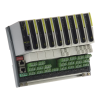
Plug in I/O modules can be fitted in three positions in the 3508 and six positions in 3504. The
positions are marked Module 1, 2, 3, 4, 5, 6. With the exception of the Analogue Input module, any
other module listed in this section, can be fitted in any of these positions. To find out which
modules are fitted check the ordering code printed on a label on the side of the instrument. If
modules have been added, removed or changed it is recommended that this is recorded on the
instrument code label.
• Hardware Code: R2 and RR
• Rating of relays: 2A, 264Vac max or 100mA, 12V
min to provide sufficient whetting current.
Plug in I/O Module Connections
Relay (2 pin) and Dual Relay Module
Change Over Relay
Voltage
supply
Contactor,
Relay, Panel
lamp etc
xC
Voltage
supply
Motorised
valve
Second relay (dual relay only)
Contactor
Relay Panel
lamp etc
Contactor
Relay Panel
lamp etc
• Hardware Code: R4
• Relay Rating: 2A, 264Vac max or 100mA, 12V
min to provide sufficient whetting current.
Triple Logic and Isolated Single Logic Output
• Hardware Code: TP and LO
• Outputs Rating: (18Vdc at 8mA max.)
• No channel isolation.
• Single Logic Output connections: D – Common
A – Logic Output
Triac and Dual Triac
• Hardware Code: T2 and TT
• Combined Output Rating: 0.7A, 30 to 264Vac
• Dual relay modules may be used in place of dual triac.
• The combined current rating for the two triacs
must not exceed 0.7A
Dual DC Output (Slots 1, 2 and 4 only)
• Hardware Code: DO
• Output Rating: each channel can be 4-20mA
or 24Vdc power supply)
High Resolution DC Retransmission & Transmitter Power Supply (Slots 1, 2 and 4 only)
• Hardware Code: HR
• Output Rating: Channel 1 (15 bit 4-20mA).
Channel 2 (24Vdc)
Snubbers
Snubbers are used to prolong the life of relay contacts and to reduce interference when switching
inductive devices such as contactors or solenoid valves. The fixed relay (terminals AA/AB/AC) is
not fitted internally with a snubber and it is recommended that a snubber be fitted externally. If
the relay is used to switch a device with a high impedance input, no snubber is necessary.
All relay modules are fitted internally with a snubber since these are generally required to switch
inductive devices. However, snubbers pass 0.6mA at 110V and 1.2mA at 230Vac, which may be
sufficient to hold on high impedance loads. If this type of device is used it will be necessary to
remove the snubber from the circuit.
The snubber is removed from the relay module as follows:-
1. Unplug the controller from its sleeve
2. Remove the relay module
3. Use a screwdriver or similar tool to snap out the track.
The view shows the tracks in a Dual Relay Output module.
Break out
tracks as
required to
disconnect
the snubber
For module functionality see ‘Quick Code’.
The function of the connections varies depending on the type of module fitted in each position and
this is shown below.
Note: The order code and terminal number is pre-fixed by the module number (x). For example,
Module 1 is connected to terminals 1A, 1B, 1C, 1D; module 2 to 2A, 2B, 2C, 2D, etc.
• All modules are isolated 240Vac CATII.
Wiring
Wire Sizes
The screw terminals accept wire sizes from 0.5 to 1.5
mm (16 to 22AWG) and should be tightened to
0.4Nm (3.5lb in). Hinged covers prevent hands or
metal making accidental contact with live wires.
1. Cut out the panel to the size shown.
To Remove the Controller from its Sleeve
Ease the latching ears outwards and pull the controller forward.
When plugging back in ensure that the latching ears click into place to maintain the IP65 sealing
Installation
Panel cut out
3504 controller A x A
A
92mm (- 0.0 + 0.8)
3.62inch
(-0.00,+0.03)
3508 controller A x B
B
45mm (
- 0.0 + 0.6)
1.77inch (-0.00,+0.02)
2. Fit the IP65 sealing gasket behind the front bezel of the instrument
3. Insert the instrument in its sleeve through the cut-out.
4. Spring the panel retaining clips into place. Secure the instrument in position by holding it level
and pushing both retaining clips forward.
5. Peel off the protective cover from the display
If the panel retaining clips subsequently need removing, they can be unhooked from the side with
either your fingers or a screwdriver.
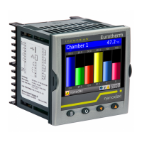
Parts Supplied and Dimensions
3508 and 3504 Process Controllers
This instrument is intended for permanent installation, for indoor use only, and to be enclosed in an
electrical panel.
Select a location where minimum vibrations are present and the ambient temperature is within 0 and
50
o
C (32 and 122
o
F).
The instrument can be mounted on a panel up to 15mm thick.
To assure IP65 and NEMA 4 front protection, use a panel with smooth surface texture.
Please read the safety information before proceeding and refer to the EMC Booklet part number
HA025464. For details not covered in this guide a 3500 Engineering Manual part no. HA027988 is
available. These documents may be downloaded from www.eurotherm.co.uk
.
ENG
HA030143/1 CN25273 03/09
PV Input
Digital
Inputs/
Outputs
Live or 24V
(2)
Neutral or 24V
(2)
Ground
Logic I/O A
Logic I/O B
Logic I/O Com
Polarising Keys (1). One per module
Power
Supply
Fixed Relay
(form C)
PV Input
T/C RTD mV mA
3504
(1) Polarising keys are intended to prevent modules,
not supported by this controller, from being fitted.
Supported modules are defined by the order code -
arrow on the polarising key points in the upward
direction when these are fitted. An example of an
unsupported module is
an unisolated module (coloured
red) from a 2400 series controller. It is possible to fit
such a module but it is the users responsibility to
ensure that it is safe to install it in the particular
application. When this has been verified the polarising
key may be adjusted with a screwdriver to point in the
down direction.
A 96mm 3.78inch
B 48mm 1.89in
C 12.5mm 0.5in
D 150mm (5.91in)
A
Latching
ears
Panel retaining
clips
Label
B
A
Controller sleeve
Terminal
block with
covers
D
C
2.49Ω resistors are
also supplied for
each mA input
(Not to scale)
C
D
A
A
B
Recommended
Minimum Spacing
C
Polarising Keys (1). One per module
Instrument Terminals
Live or 24V
(2)
Neutral or 24V
(2)
Ground
Logic I/O A
Logic I/O B
Logic I/O Com
MODULE 1
MODULE 2 MODULE 3
Power
Supply
Digital
Inputs/
Outputs
Fixed Relay
(form C)
3508
• Hardware Code: D4
• Output Rating: (10Vdc, 20mA max)
DC Control
DC Retransmission
• Hardware Code: D6
• Output Rating: (10Vdc, 20mA max)
Triple Logic Input
• Hardware Code: TL
• Input Ratings: Logic inputs <5V OFF >10.8V ON
Limits: -3V, +30V
Triple Contact Input
• Hardware Code: TK
• Input Ratings: Logic inputs >28K OFF <100 ON
24V Transmitter Power Supply
• Hardware Code: MS
• Output Rating: 24Vdc 20mA
Potentiometer Input
• Hardware Code: VU
• Rating: 100Ω to 15KΩ
Plug in I/O Module Connections (continued)
Transducer Power Suppy
Transducer with Internal Calibration Resistor
Actuator
0-20mA
or
0-10Vdc
xA
xB
To other
controllers
0-20mA
or
Input 3
External
Switches
or Relays
• Hardware Code: G3
• Rating: Configurable 5V
or 10Vdc.
• Minimum load resistance
300Ω
Internal
switch to
connect
Rcal
V+
V-
Transducer with External Calibration Resistor
Input if an analogue input module is used in
the appropriate slot.
C
D