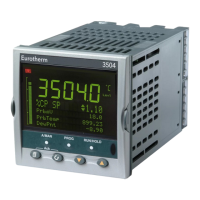
Do you have a question about the Eurotherm 3500 series and is the answer not in the manual?
| Controller Type | Process controller |
|---|---|
| Power Supply | 24V AC/DC, 100-240V AC |
| Input Types | Thermocouple, RTD |
| Output Types | Relay, SSR Drive |
| Control Modes | PID, On/Off |
| Operating Temperature | 0°C to 55°C |
| Control Output | Relay |
| Communication | Modbus RTU |
Explains how to interpret the hardware and options coding for ordering.
Details the quick start code for factory configuration.
Diagrams and details for wiring the controller's electrical terminals.
How to connect the controller's power supply.
How to install and connect various plug-in I/O modules.
Wiring for various analogue input types.
How to connect communication modules like Modbus, DeviceNet, Profibus.
Guide for initial setup and configuration of a new controller.
Step-by-step process for configuring parameters in Quick Start.
Lists and explains parameters available in Quick Start mode.
Instructions on how to access Quick Start mode again.
How to adjust the setpoint value for the loops.
How to switch between Auto and Manual control modes.
How alarms are displayed and indicated on the controller.
Steps to acknowledge active alarms.
How sensor failure or open circuits are indicated.
General guidance on editing parameters.
Procedures for accessing higher security levels for configuration.
Steps to select, run, hold, or reset a program.
How to view and modify the status of a running program.
Interface for creating or editing programs.
Detailed steps for program creation and editing.
Compliance with safety standards and directives.
Compliance with EMC directives and standards.
Safety warning regarding stored electrical charge.
Precautions to prevent damage from static electricity.
Requirements for safe installation, including symbols and personnel.
Specifies that installation must be done by qualified personnel.
Requirement to enclose live parts for safety.
Guidelines for safe and compliant wiring practices.
Requirement for a power isolating switch or circuit breaker.
Importance of proper fusing for the power supply.
Essential considerations for preventing overheating.
Precautions for ensuring electromagnetic compatibility during installation.